
A fast detection device for electric meter
A technology of detection device and electric meter, applied in the direction of measurement device, measurement of electrical variables, instruments, etc., can solve the problem of low test efficiency, achieve the effect of fast and convenient detection, improve detection efficiency, and improve work efficiency
- Summary
- Abstract
- Description
- Claims
- Application Information
AI Technical Summary
Problems solved by technology
Method used
Image

Examples
Embodiment 1
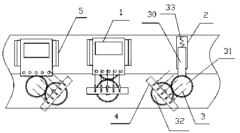
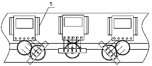
[0023] Such as figure 1 , 2 As shown, a fast detection device for an electric meter includes a conveyor belt, and a fixed block 4 is arranged on one side of the conveyor belt. The fixed block is provided with a probe 3 for realizing contact and electrical connection with the terminal post of the electric meter 1, and the probe is connected with a wire. The wires are used to connect the detection instrument, the probes are in groups, the number of probes in each group is equal to the number of binding posts of each ammeter, the spacing of the probes is equal to the spacing of the binding posts, and the fixed block is set at On the first gear 31 that rotates freely around the fixed shaft, the fixed shaft is fixed relative to the conveyor belt, and the conveyor belt is provided with a chute perpendicular to the conveying direction of the conveyor belt. A slide bar 30 is slidably arranged in the chute 2, and the bottom end of the slide bar is connected with the slide bar. A sprin...
Embodiment 2
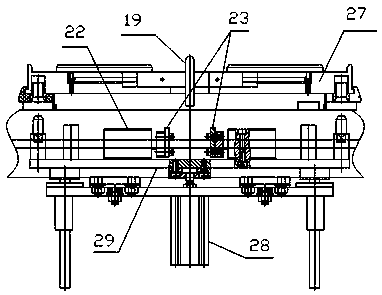
[0027] Such as image 3 , 4 As shown, different from the above-mentioned embodiment, the tray fixed on the slide bar is the electric meter placement box 27, and the box bottom of the electric meter placement box is provided with left and right two pairs of jaws 19, 20, and the jaws can slide Set on the chute 21 at the bottom of the box, a return spring is arranged between the jaws and the chute, the return spring makes the two pairs of jaws clamp the meter, the lower end of the jaws has a lower end protruding from the bottom of the box, and there are two under the bottom of the box Two oppositely arranged push cylinders 22, two cylinder pistons are provided with jaw push plates 23, and the two push plates push the lower ends of the jaws simultaneously, so that the distance between the two pairs of jaws becomes larger. The push plate is controlled by the lifting mechanism, and the push cylinder is flatly placed on the plate body 28, and the plate body is controlled by the plat...
Embodiment 3
[0029] Such as Figure 5 , 6 , 7, the conveyor belt includes two cross conveyor belts and is defined as a horizontal conveyor belt 8 and a vertical conveyor belt 9, wherein one of the conveyor belts is provided with an electric meter transplanting mechanism, and the transplanting mechanism includes a support plate 10, and the support plate is placed on the conveyor belt, A lifting plate 11 is arranged on the supporting plate, and a telescopic control mechanism is arranged between the lifting plate and the supporting plate to control the lifting of the lifting plate relative to the supporting plate, such as a lifting control cylinder 12, and a horizontal rotating shaft 14 driven by a motor 13 is arranged below the supporting plate. Pulleys 15 are arranged at both ends of the rotating shaft, and a belt 16 is wound around each pulley, and the belt goes around the lifting plate at the same time, and the corresponding belt is provided with a guide wheel on the lifting plate to faci...
PUM
 Abstract
Description
Claims
Application Information