A circular blade and cutting tool with accurate positioning structure

An accurate positioning and round blade technology, applied in the field of cutting, can solve the problems of round blade chipping, cutting life, low cutting efficiency, fastener deformation, etc., to avoid cutting vibration, improve cutting accuracy, and improve clamping rigidity Effect

Active Publication Date: 2020-08-07
ZHUZHOU CEMENTED CARBIDE CUTTING TOOLS CO LTD
View PDF8 Cites 0 Cited by
  • Summary
  • Abstract
  • Description
  • Claims
  • Application Information

AI Technical Summary

Problems solved by technology

[0003] Although the round blade has the above advantages when it is clamped and cut through the center hole, the center of the fastener and the center axis of the round blade are not concentric. When clamping, only a small area of ​​contact with the center hole of the round blade can be produced, even if it can be provided to the round blade. Sufficient clamping force, but the round blade is also prone to rotation, and the fastener is prone to multi-directional deformation during cutting, which induces cutting vibration. Short cutting life due to chipping

Method used


Image

  • A circular blade and cutting tool with accurate positioning structure
  • A circular blade and cutting tool with accurate positioning structure
  • A circular blade and cutting tool with accurate positioning structure

Examples


Embodiment 1

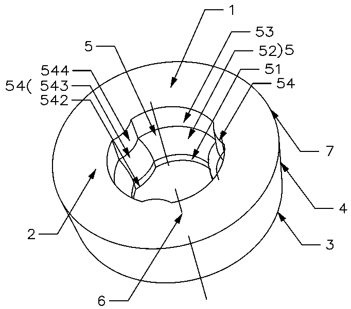
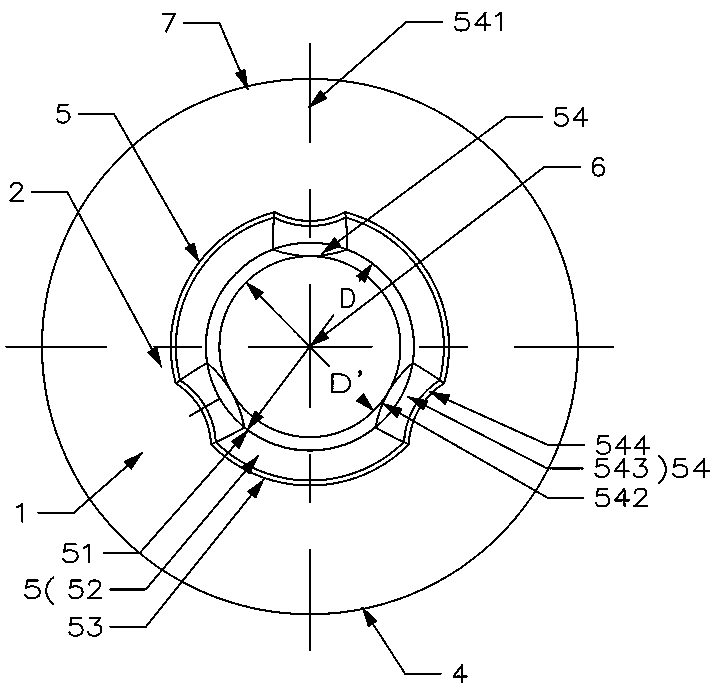
[0035] Such as Figure 1 to Figure 4 As shown, the circular blade with an accurate positioning structure in this embodiment includes a circular plate-shaped blade body 1 composed of an upper surface 2, a lower surface 3, and a side 4 connecting the upper surface 2 and the lower surface 3. The blade body 1 There is a central hole 5 that runs through the upper surface 2 and the lower surface 3. The blade body 1 is symmetrical about the central axis 6 of the central hole 5. The upper surface 2 intersects with the side 4 to form a cutting edge 7. The inner surface of the central hole 5 is provided with at least two protruding portions, the angle between two adjacent protruding portions 54 is less than 180°.

[0036] In this embodiment, taking three protrusions 54 as an example, each protrusion 54 is uniformly arranged along the circumferential direction of the central hole 5 . Each protrusion 54 is provided with a protrusion symmetry plane 541 .

[0037] In this example, if im...

Embodiment 2

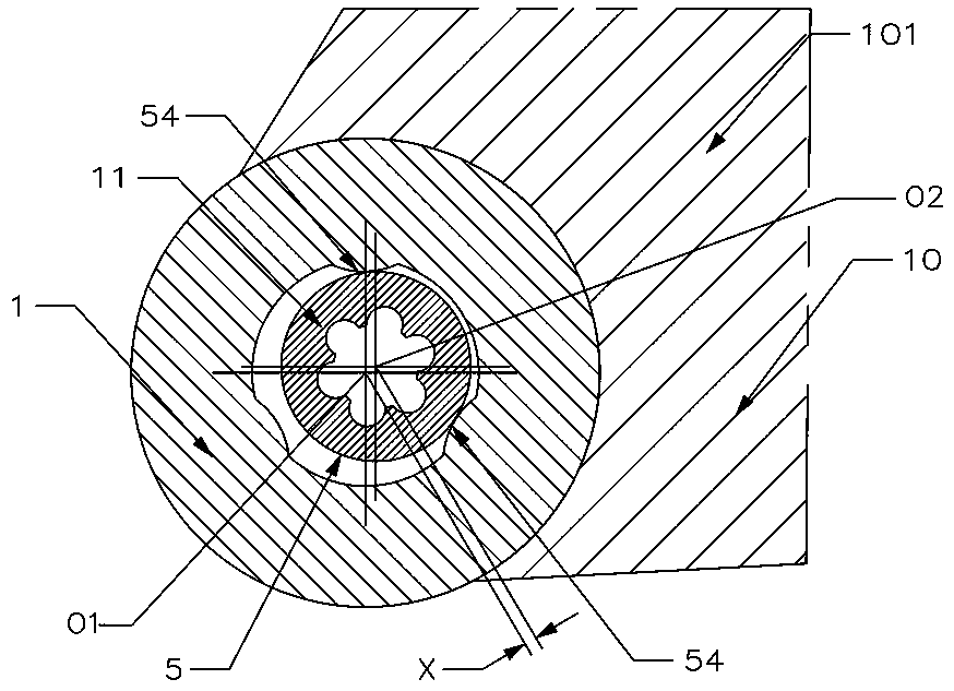
[0042] Such as Figure 5 As shown, the cutting tool of the present embodiment includes a cutter body 10 and a fastening screw 11. The cutter body 10 is provided with a sipe 101. The cutting tool includes the round blade in Embodiment 1, and the round blade is installed in the sipe 101. , the fastening screw 11 is in contact with at least two protrusions 54 in the central hole 5 , and presses the blade body 1 into the knife groove 101 . When the deformation of the fastening screw 11 increases with the increase of the cutting force, the third protrusion 54 will also come into contact with the fastening screw 11 , thereby finally forming a triple-constrained over-clamping positioning.

[0043] In this embodiment, since there are three protrusions 54, the circular blade can be rotated three times and installed and positioned three times.

[0044] In order to ensure that the blade body 1 is installed in the knife groove 101 for use, the adjacent two protrusions 54, the third protr...

Embodiment 3

[0048] Such as Figures 6 to 9 As shown, this embodiment is substantially the same as Embodiment 1, the difference is that in this embodiment, there are four raised portions 54, and a corner raised portion is provided between two adjacent raised portions 54 55, with four corner protrusions 55 in total.

[0049] In this embodiment, each protrusion 54 is provided with a protrusion symmetry plane 541, the corner protrusion 55 has a corner protrusion symmetry plane 551, the protrusion symmetry plane 541 and the corner protrusion symmetry plane 551 Both pass through the central axis 6. The purpose of setting the corner protrusion 55 is: when the fastening screw 11 is tightened, when the fastening screw 11 is pressed against the two adjacent protrusions 54, it will be raised with the corner between the two protrusions 54 at the same time. The part 55 is pressed tightly, and the three-point contact between the fastening screw 11 and the inner surface of the center hole 5 is realize...


PUM


Abstract

The invention discloses a circular blade with an accurate positioning structure and a cutting tool. The circular blade comprises a blade body, wherein the blade body is composed of an upper surface, a lower surface and a side face which is used for connecting the upper surface with the lower surface; and the blade body is provided with a center hole which penetrates through the upper surface and the lower surface, the blade body is centrosymmetric relative to the central axis of the center hole, the upper surface intersects with the side face to form a cutting edge, the inner surface of the center hole is provided with at least two lug bosses, and the included angle between every two adjacent lug bosses is smaller than 180 degrees. The cutting blade has the advantages that positioning is reliable and stable, multi-ply clamping can be achieved, and the service life is long. The cutting tool is provided with the circular blade, sliding or rotating of the circular blade in the peripheral direction in the using process can be eliminated, the stability of the cutting edge in a cutting region is guaranteed, other cutting processes are prevented from participating in one cutting process, the usable frequency of the circular blade on the cutting tool is effectively stabilized, and then the service life of the cutting tool is prolonged.

Description

technical field [0001] The invention relates to cutting processing technology, in particular to a circular blade and a cutting tool with an accurate positioning structure. Background technique [0002] During the cutting process of the blade, the clamping strength and rigidity of the circular blade have a great influence on the cutting ability of the circular blade, and the clamping stability of the cutting slice especially has a substantial impact on the cutting efficiency and cutting accuracy of the circular blade. The circular blade with stable clamping not only has high cutting efficiency, precision but also has a long life. The vibration of the circular blade with unstable clamping is easy to produce during cutting, which will cause the rapid wear or even collapse of the circular blade, which greatly shortens the life of the circular blade. . In order to improve the cutting performance of round blades in the industry, round blades are designed into a variety of round b...

Claims


Application Information

Patent Timeline
Patent Type & Authority Patents(China)
IPC IPC(8): B26D1/14B26D1/143
CPCB26D1/14B26D1/143
Inventor 江爱胜王社权刘敏向兴东李屏汤爱民
Owner ZHUZHOU CEMENTED CARBIDE CUTTING TOOLS CO LTD
Why Eureka
Try Eureka