Magnetic separator

A magnetic separation and rack technology, applied in high gradient magnetic separators and other directions, can solve the problems affecting the normal operation of the equipment and the sorting efficiency, increasing the height of the feeding and discharging direction, and the high moisture content of the discharge material, so as to solve the problem of flushing. Good unloading effect, reduce waste of resources, and solve the sorting effect

Pending Publication Date: 2018-01-09
广东省资源综合利用研究所
View PDF0 Cites 9 Cited by
  • Summary
  • Abstract
  • Description
  • Claims
  • Application Information

AI Technical Summary

Problems solved by technology

This structure increases the height of the feeding and discharging direction (magnetic media sorting height). Although the sorting effect is improved, it will cause the flushing and discharging height to increase at the same time, and it is difficult for the flushing water to penetrate through the thick media box effectively. There are more and more residual magnetic substances, the sorting effect of the equipment is getting worse and worse, and even the media box is blocked, which seriously affects the normal operation of the equipment and the sorting efficiency
Moreover, the mixed arrangement of magnetic permeable materials in the direction of the separation height of magnetic media in this structure will also increase the difficulty of washing and unloading
In addition, the existing flushing and unloading method has a high water content in the unloaded material, which is not conducive to subsequent processing

Method used


Image

  • Magnetic separator
  • Magnetic separator
  • Magnetic separator

Examples


Embodiment Construction

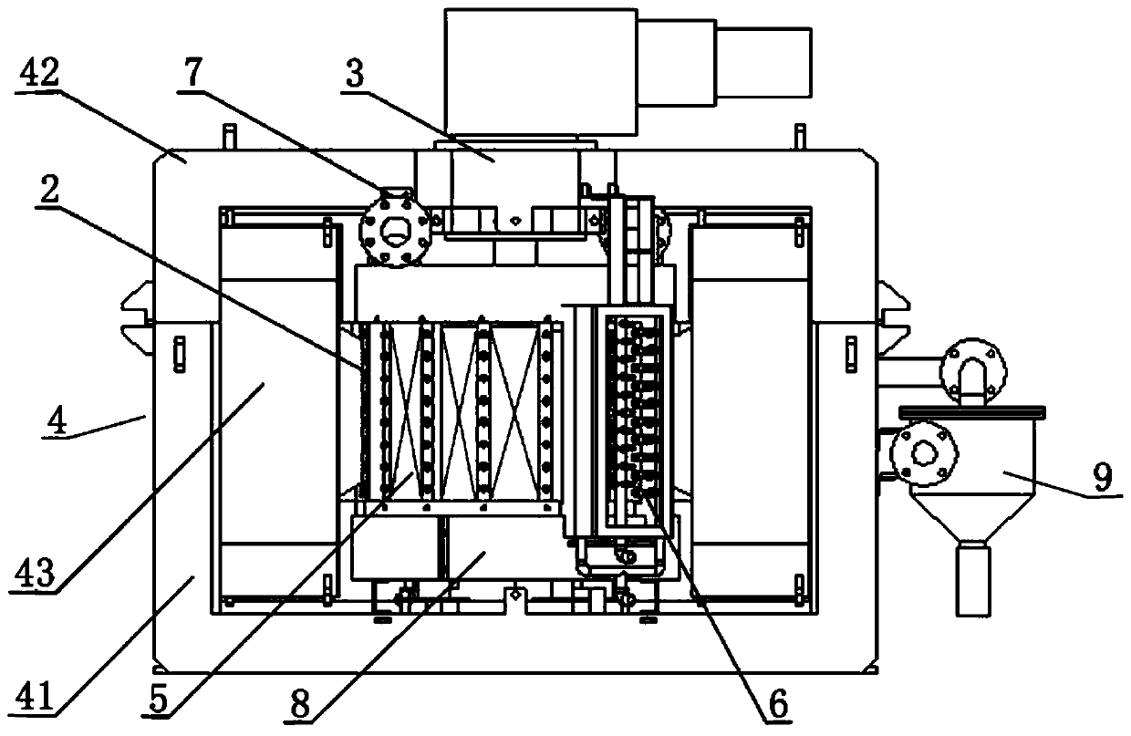
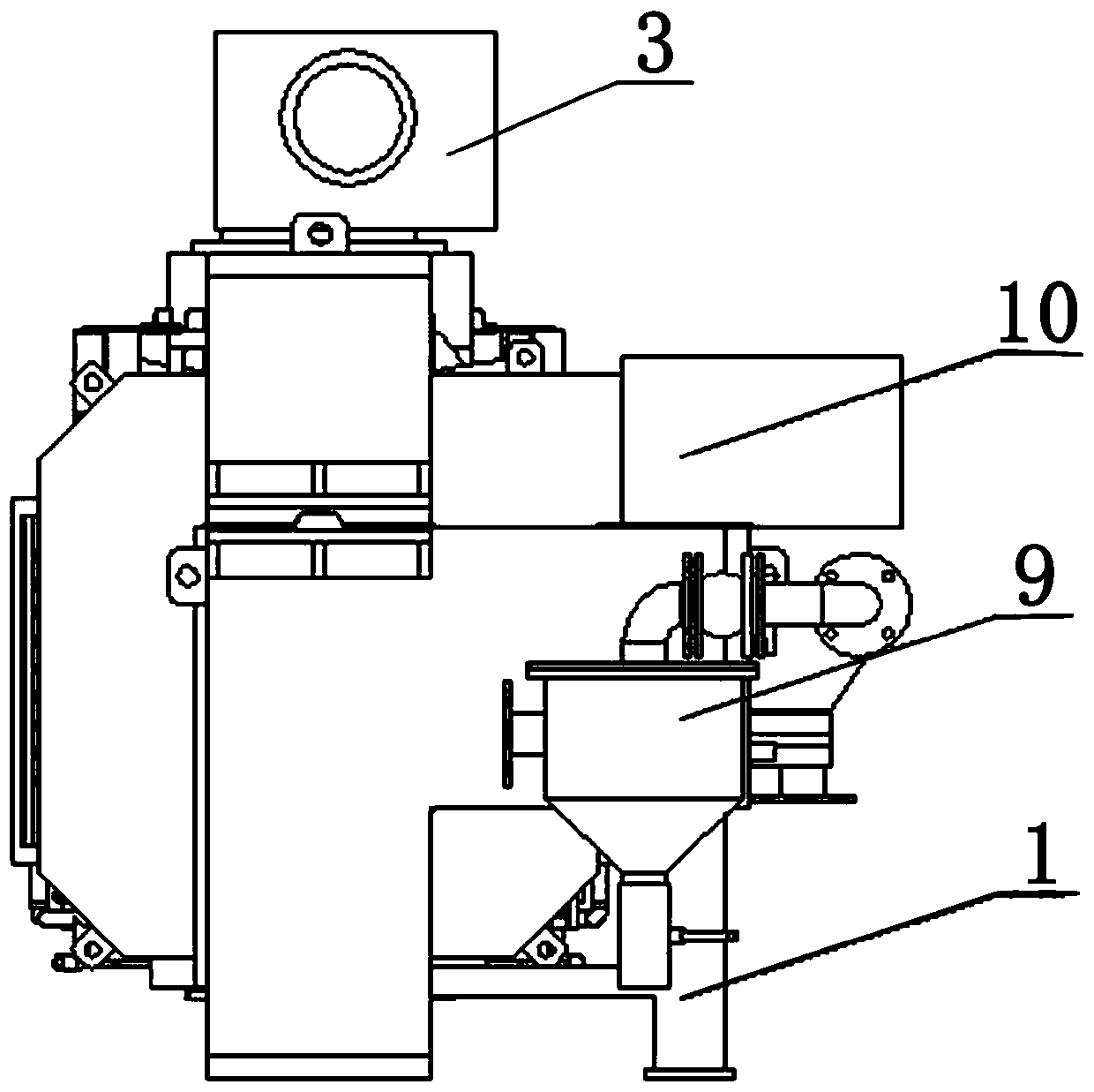
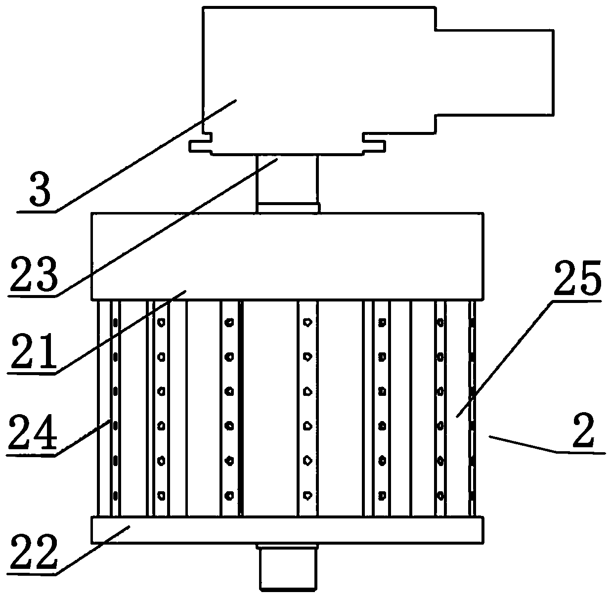
[0027] Such as Figure 1-Figure 7 As shown, the magnetic separator of the present invention includes a frame 1, a swivel 2, a horizontal rotation drive mechanism 3 and a magnetic field for generating a horizontal separation magnetic field and the magnetic field strength can reach a maximum of 1.8T. Excitation device 4. Wherein, the swivel 2 is provided with a mixed medium box 5, the thickness of the mixed medium box 5 along the flushing and discharging direction is between 10-600 mm, and its sorting height is between 20-3000 mm. Such as Figure 5 As shown, in this embodiment, the mixed medium box 5 is composed of a medium plate 51 and magnetically permeable stainless steel rods 52 and magnetically permeable stainless steel expanded mesh 53 mixedly arranged on the medium plate 51 along the separation height direction. Of course, the mixed medium box 5 can also be in other structural forms. For example, the mixed medium box 5 is composed of a medium plate and magnetically cond...


PUM


Abstract

A magnetic separator, comprising a frame, a rotating ring, a horizontal rotation drive mechanism and an excitation device arranged on the frame for generating a horizontal separation magnetic field, the rotating ring is provided with a mixed media box, and the rotating ring There is a water-air combined flushing device for flushing and discharging the mixed media box from the side. The material enters from the upper end of the swivel and is discharged from the lower end of the swivel after sorting. The direction of feeding and discharging is the same as that of the rotary ring. The washing discharge direction is vertical. Since the present invention adopts a structure in which the direction of feeding and discharging is perpendicular to the direction of flushing and discharging, as long as the thickness of the sorting medium box (flushing and discharging depth) remains unchanged, the sorting height of the medium box can be designed according to the magnetic performance requirements of the sorting material , without affecting the washing and unloading effect of the media box, ensuring the stable and continuous operation of the equipment without clogging; the use of the mixed media box improves the sorting gradient and effectively improves the sorting effect; the water-air combined flushing device on the side effectively It reduces the moisture content of the unloading material, reduces the difficulty of subsequent processing, and provides reliable and practical technical equipment for the sorting of weak magnetic materials.

Description

technical field [0001] The invention relates to a continuous high-gradient magnetic separator, in particular to a horizontal side flushing high-gradient magnetic separator for sorting weak magnetic substances. Background technique [0002] Continuous high-gradient magnetic separators are divided into vertical ring high-gradient magnetic separators and horizontal high-gradient magnetic separators. Widely used in mining enterprises and sewage treatment enterprises at home and abroad, it is one of the most important equipment for wet separation of weak magnetic substances. [0003] In recent years, with the gradual depletion of mineral resources in my country and the world, the price of mineral resources has continued to rise, and more and more low-grade weak magnetic mineral resources (iron ore, manganese ore, etc.) are urgently needed to be developed and utilized; on the other hand, industrialized Development has higher and higher requirements for products, and it is more and...

Claims


Application Information

Patent Timeline
Patent Type & Authority Applications(China)
IPC IPC(8): B03C1/025B03C1/031B03C1/032
Inventor 张军徐少华林恬盛刘建国汤玉和何健全张红英
Owner 广东省资源综合利用研究所
Why Eureka
Try Eureka