
A rotary low-impact self-separating pressing and releasing device
A release device and low-impact technology, applied in the field of remote sensing satellites, can solve problems such as sensitivity, payload damage, and large impact, and achieve high rigidity, provide connection stiffness, and high connection stiffness
- Summary
- Abstract
- Description
- Claims
- Application Information
AI Technical Summary
Problems solved by technology
Method used
Image

Examples
Embodiment Construction
[0025] The present invention will be described in detail below with reference to the accompanying drawings and examples.
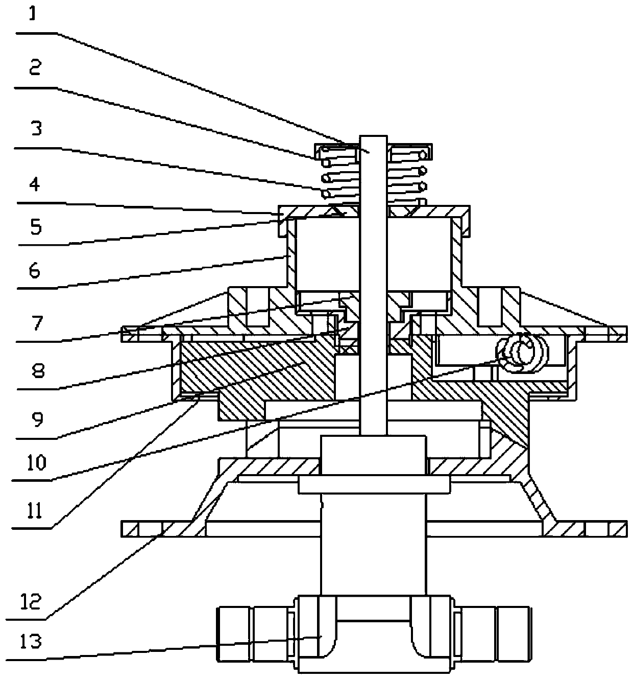
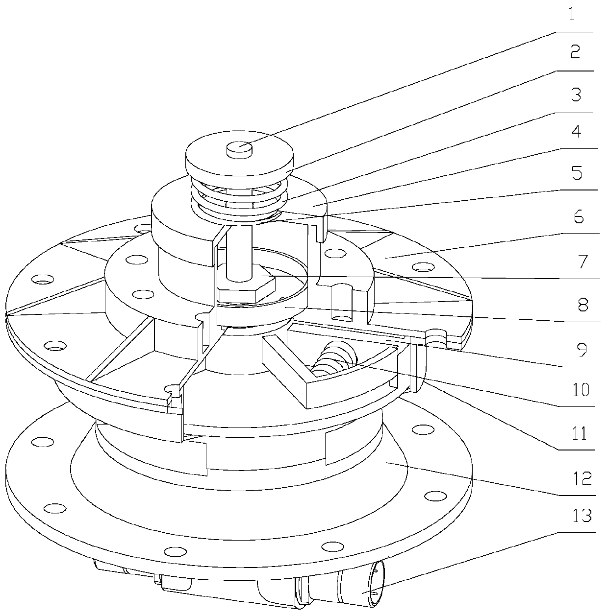
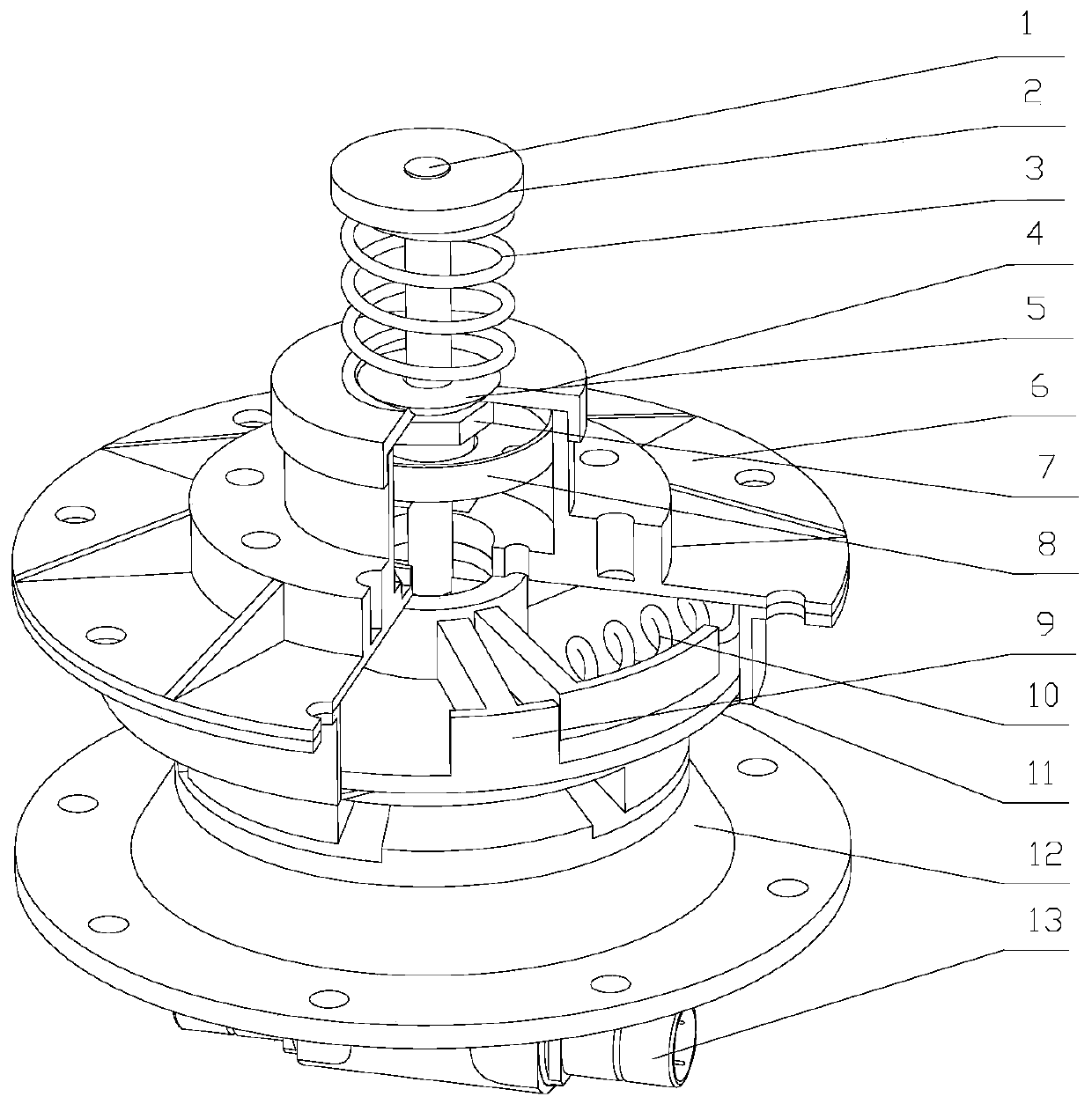
[0026] The invention provides a rotary low-impact self-separation compression release device, which comprises a compression rod 1, a compression cap 2, a separation spring 3, an upper end cover 4, a ball cushion 5, an upper base 6, a compression Tight nut 7, limit block 8, rotating lock flap 9, unlocking spring 10, shell 11, lower base 12 and separation nut 13, such as figure 1 shown.
[0027] The bottom of the upper base 6 is provided with three stoppers, which are evenly arranged on the bottom of the upper base 6; the top of the rotary lock flap 9 is provided with three stoppers, which are evenly arranged on the top of the rotary lock flap 9, and the bottom of the rotary lock flap 9 is provided with conical teeth. There are three shaped teeth, and a wedge-shaped groove is provided in the middle of the rotating lock flap 9; the top of the lower base 12 i...
PUM
 Abstract
Description
Claims
Application Information