Method and system for measuring polarization state of sample based on polarization beam splitting prism

A polarization beam splitting prism and polarization state technology, applied in the fields of optics and digital holography, can solve the problems of limited accuracy and cumbersome process, and achieve the effect of improving the ability of real-time measurement

Active Publication Date: 2018-05-04
NORTHWESTERN POLYTECHNICAL UNIV
View PDF4 Cites 7 Cited by
  • Summary
  • Abstract
  • Description
  • Claims
  • Application Information

AI Technical Summary

Problems solved by technology

However, the commonly used digital holography can only obtain the amplitude and phase information of the light field to be measured, and the polarization state information carried by the object is also one of its most important properties.
The Mueller microscope currently used in biology can measure the Mueller matrix of biological tissues, but it needs to adjust the polarization state of the incident light multiple times and record multiple sets of intensity information to decipher the polarization information of biological tissues. The process is very cumbersome and the accuracy is limited.

Method used


Image

  • Method and system for measuring polarization state of sample based on polarization beam splitting prism
  • Method and system for measuring polarization state of sample based on polarization beam splitting prism
  • Method and system for measuring polarization state of sample based on polarization beam splitting prism

Examples


Embodiment 1

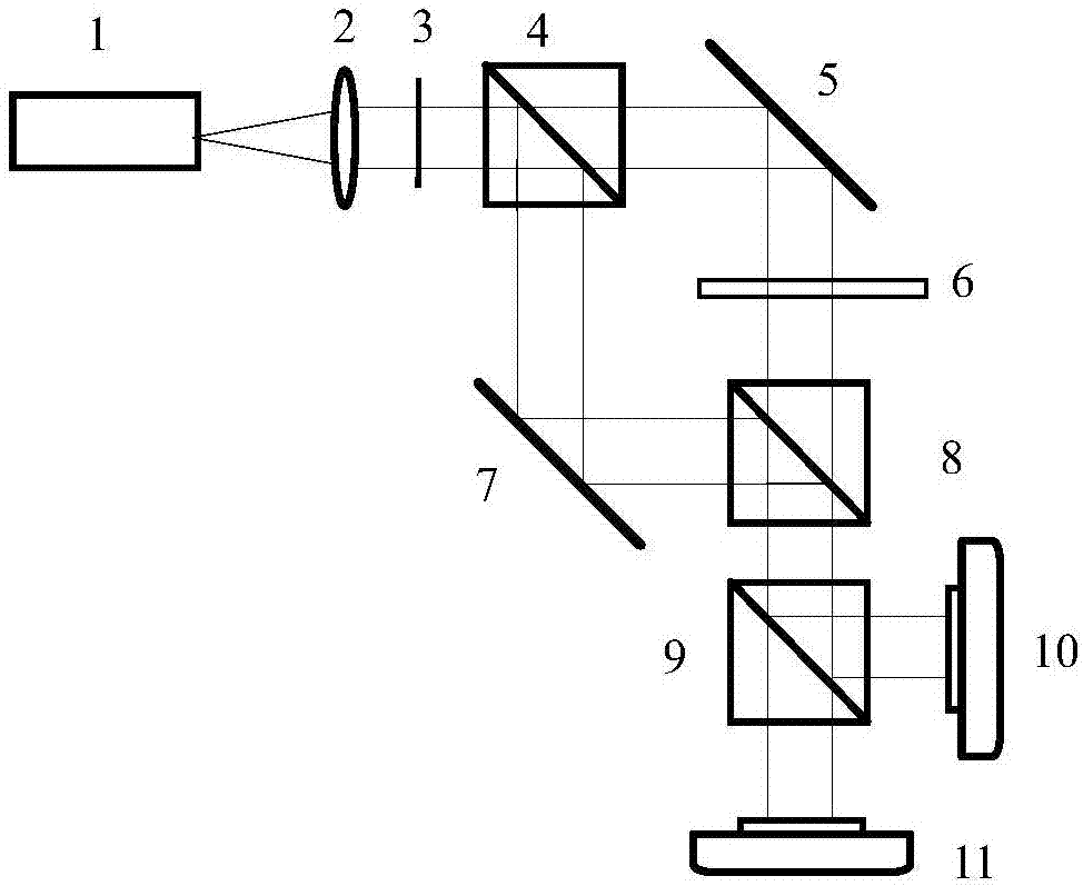
[0032] Embodiment 1: A kind of transmission type sample polarization state information measurement system based on polarization beam splitter prism designed by the present invention such as figure 2 As shown, the workflow is as follows:

[0033] The light emitted by the laser 1 is collimated into a beam of parallel light by the lens group 2, modulated by the polarizer 3, and enters the non-polarizing beam-splitting prism 4, and is divided into two beams of parallel light by the non-polarizing beam-splitting prism 4, one of which is captured by the reflector 5 After reflection, it is modulated by the transmissive sample 6 as the object beam and enters the non-polarizing beam-splitting prism 8, and another beam of light is reflected by the mirror 7 and then enters the non-polarizing beam-splitting prism 8 as a reference beam. The use of the non-polarizing beam-splitting prism 8 makes the reference beam The object beam and the object beam are simultaneously incident on the polar...

Embodiment 2

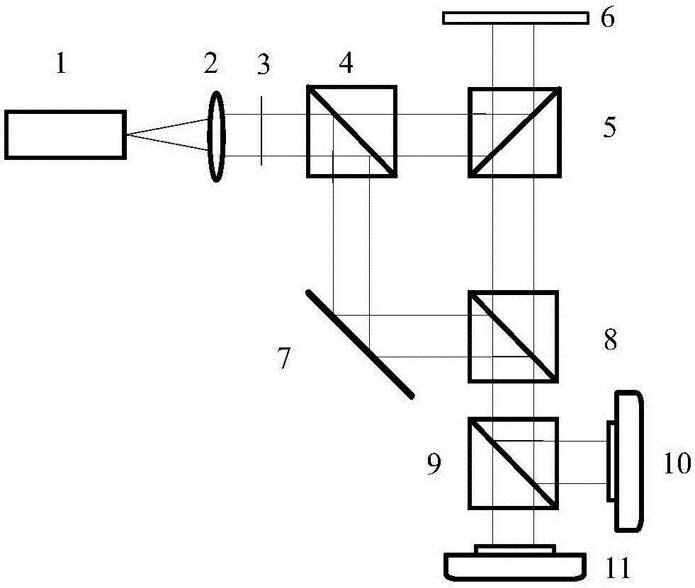
[0035] Embodiment 2: The optical path of a reflective sample polarization measurement system based on a polarization beam splitter designed by the present invention is as follows image 3 As shown, the workflow is as follows:

[0036] The light emitted by the laser 1 is collimated into a beam of parallel light by the lens group 2, and the polarization state is modulated by the polarizer 3, and then enters the non-polarizing beam-splitting prism 4, and is divided into two beams of parallel light by the non-polarizing beam-splitting prism 4, one of which is filtered by the non-polarizing beam-splitting prism 4. After being reflected by the polarizing beamsplitter prism 5, it is reflected by the reflective sample 6 as the object beam and enters the non-polarizing beam-splitting prism 8, and the other beam of light is incident on the non-polarizing beam-splitting prism 8 as a reference beam after being reflected by the reflector 7, and the non-polarizing beam-splitting prism 8 make...


PUM


Abstract

The invention discloses a method and system for measuring a polarization state of a sample based on a polarization beam splitting prism. After light emitted by a laser device is aligned through an alignment device, the light is split into two beams through a non-polarization beam splitting prism, wherein one beam of light penetrates through a sample or carries sample information after being reflected by the sample and is used as an object light beam; the other beam of light is used as a reference light beam; the two beams of light are reflected through a reflecting mirror and then are converged through the non-polarization beam splitting prism. The polarization beam splitting prism is rotated so that the reference light beam is divided into two beams of linearly polarized light, which havebasically equal light intensity and crossed polarization directions, after passing through the polarization beam splitting prism. After the reference light beam and the object light beam pass throughthe polarization beam splitting prism, two interference patterns with orthogonal polarization states are formed. Two holograms are recorded by utilizing a camera. A computer is used for further carrying out numerical value reconstruction on complete unification positions and corresponding pixel points of the sample in the two holograms; finally, corresponding amplitude and phase information of anobject light wave field is finally obtained; the information is processed by the computer to obtain polarization state information of the sample. Compared with utilization of a traditional Mueller microscope, a condition that a plurality of times of acquisition are influenced by the environment is avoided and the stability and the real-time measurement capability of the system are improved.

Description

technical field [0001] The invention relates to the field of optics, in particular to the field of digital holography technology. Background technique [0002] Digital holography is widely used in fields such as flow field measurement, deformation measurement, shape analysis, and microscopic imaging due to its advantages of fast real-time, non-destructive, non-invasive, and full-field measurement. However, the commonly used digital holography can only obtain the amplitude and phase information of the light field to be measured, and the polarization state information carried by the object is also one of its most important properties. The Mueller microscope currently used in biology can measure the Mueller matrix of biological tissue, but it needs to adjust the polarization state of the incident light multiple times and record multiple sets of intensity information to decipher the polarization information of biological tissue. The process is very cumbersome and the accuracy is...

Claims


Application Information

Patent Timeline
Patent Type & Authority Applications(China)
IPC IPC(8): G01N21/21
CPCG01N21/21
Inventor 邸江磊王凯强豆嘉真赵建林
Owner NORTHWESTERN POLYTECHNICAL UNIV
Why Eureka
Try Eureka