
Intelligent railway inspection equipment
A track and intelligent technology, applied in the direction of TV, instruments, measuring devices, etc., can solve the problems of inability to touch the switch, reduce the work intensity of personnel, and the bolts are locked and difficult to rotate, so as to achieve remote control, positioning and tracking, and good use prospects Effect
- Summary
- Abstract
- Description
- Claims
- Application Information
AI Technical Summary
Problems solved by technology
Method used
Image

Examples
Embodiment Construction
[0017] In order to make the technical means, creative features, goals and effects achieved by the present invention easy to understand, the present invention will be further described below in conjunction with specific embodiments.
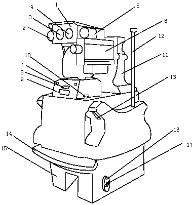
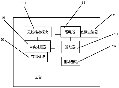
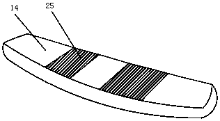
[0018] Such as Figure 1-3 As shown, a kind of intelligent track inspection equipment includes a cloud platform 1, a pickup 2 is fixedly installed on the outer surface of one side of the cloud platform 1, and an infrared thermal imager 3 is arranged on the outer surface of the front end of the cloud platform 1, which is close to the cloud platform 1 One side of the front-end outer surface infrared thermal imager 3 is provided with a visible light camera 4, and the other side outer surface of the cloud platform 1 is fixedly equipped with a night vision light 5, and the other side outer surface night vision light 5 near the cloud platform 1 A laser vibrometer 6 is provided below the laser vibrometer 6, a radar 7 is provided below the laser vibromete...
PUM
 Abstract
Description
Claims
Application Information