Peristaltic pump device

A technology of peristaltic pumps and rotating positions, applied in pumps, parts of pumping devices for elastic fluids, pump control, etc., can solve problems such as difficult to reduce pulsation, fluid pulsation, etc.

Inactive Publication Date: 2018-06-05
TAKASAGO ELECTRIC
View PDF5 Cites 6 Cited by
  • Summary
  • Abstract
  • Description
  • Claims
  • Application Information

AI Technical Summary

Problems solved by technology

[0009] However, in this peristaltic pump, the roller can crush the arc-shaped flow path with a very small load to feed liquid, so the rotational load of the rotor can be reduced and the motor can be downsized, and when the cover is removed, the It is difficult to reduce the pulsation because the pulsation of the fluid still occurs even if the micro-channel chip is replaced easily.

Method used


Image

  • Peristaltic pump device
  • Peristaltic pump device
  • Peristaltic pump device

Examples


Embodiment Construction

[0046] Hereinafter, the present invention will be described based on the embodiments shown in the drawings. In addition, this invention is not limited to embodiment. All changes in the elements of the claims or equivalent elements related to the elements are included in the scope of the claims.

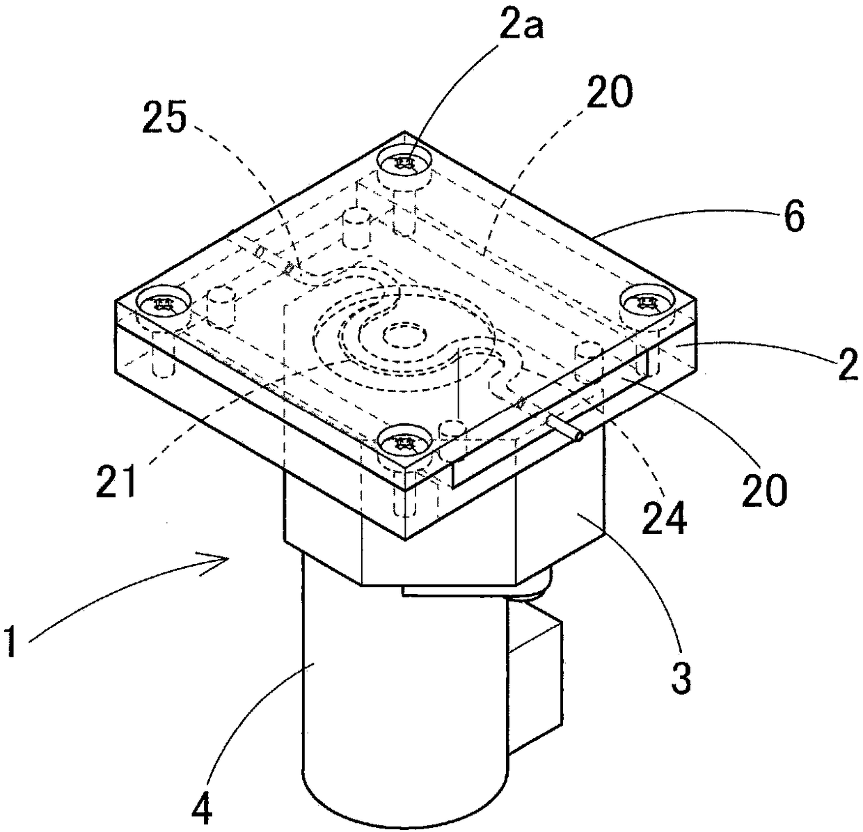
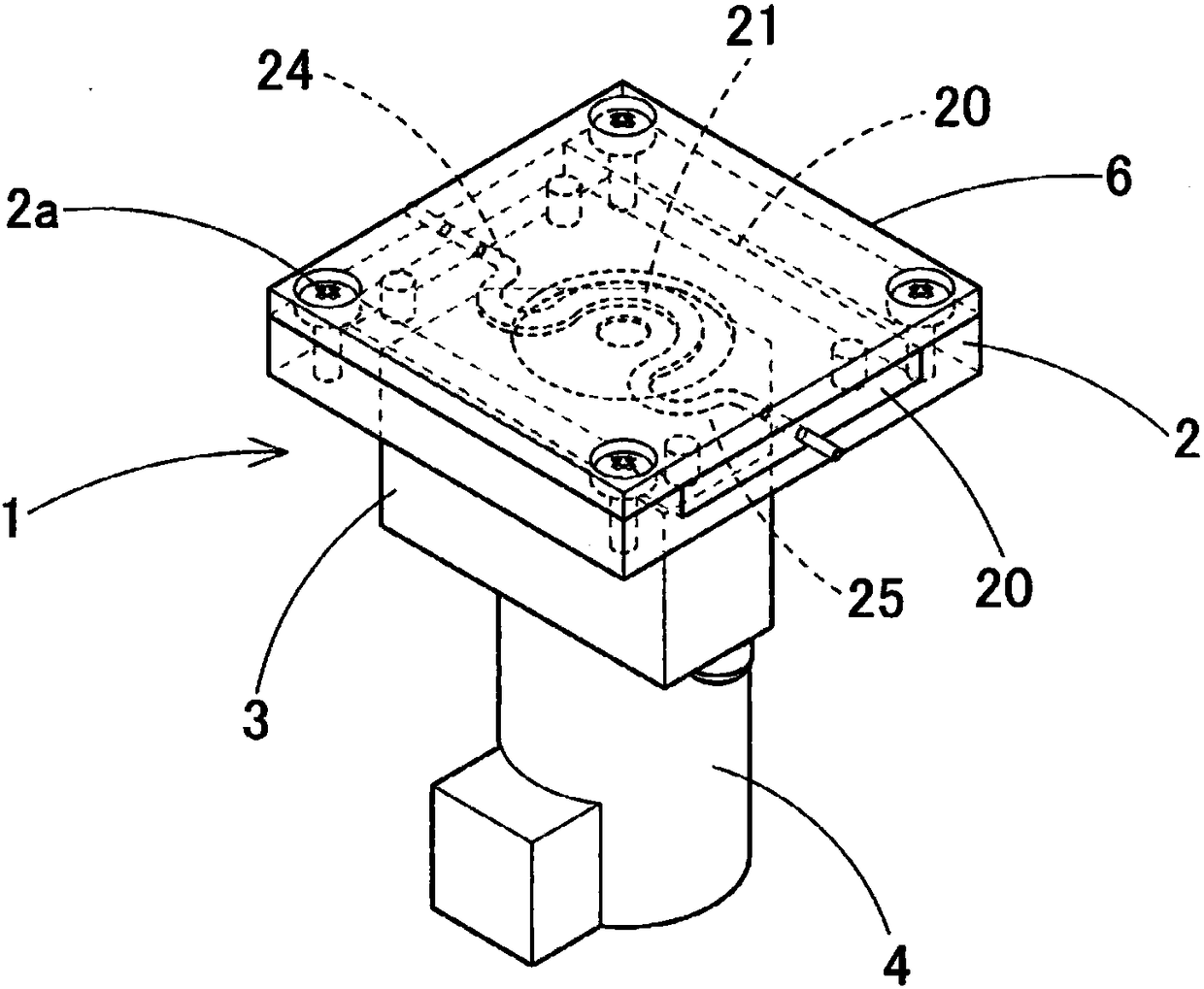
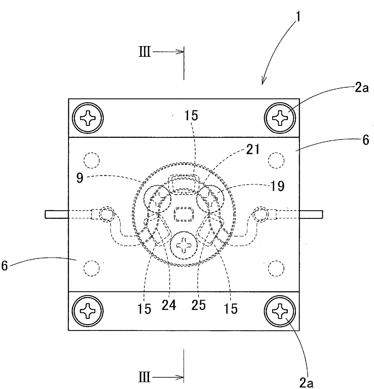
[0047] Figure 1~ Figure 17 Represents the peristaltic pump device of the first embodiment, such as Figure 15 As shown, the peristaltic pump device is composed of: a base 2, which is used to accommodate a microfluidic chip 20; a micro peristaltic pump 1, which is fixed on the lower part of the base 2, and uses a motor 4 to drive the rotor 10; and a control circuit 30, It is used to control the rotational speed of the motor 4 .

[0048] In the miniature peristaltic pump 1, the rotor 10 that can be driven by the motor 4 is installed on the upper part of the miniature peristaltic pump 1, and three rollers 15 are radially supported on the rotor 10 at intervals on the horizontal plane ...


PUM


Abstract

A micro peristaltic pump of a peristaltic pump device presses a rotor against a circular arc shaped flow path inside a microfluidic chip formed to be sheet-like, rotary-drives the rotor by a motor, and causes the circular arc shaped flow path to make a peristaltic motion by the rotation of the rotor, to send a fluid. The peristaltic pump device is provided with a rotation sensor that detects a rotational position of the rotor, a memory that stores in advance a rotational position of the rotor and rotation speed data of the motor corresponding to the rotational position, and a control circuit that calculates a command rotation speed of the motor from data stored in the memory based on a detection signal of the rotation sensor, and controls rotation of the motor based on the command rotationspeed.

Description

technical field [0001] The present invention relates to a peristaltic pump device for cell culture, reagent screening, chemical analysis, etc. by making microfluids such as culture medium and various reagents flow through microfluidic channels, and in particular to a peristaltic pump device that can effectively reduce A peristaltic pump unit that minimizes pulsation when delivering fluid. Background technique [0002] Conventionally, a peristaltic pump is known from Japanese Patent Application Laid-Open No. 2004-92537. In this peristaltic pump, a plurality of rollers are rotatably supported on a circular rotor, and the outer peripheral surface of each roller of the rotor is pressed against the hose. While rotating the rotor, the fluid in the hose is conveyed. [0003] In the conventional peristaltic pump of this type, a plurality of rollers are rotatably supported on the outer peripheral portion of a circular rotor that is rotationally driven by a motor, and the support sha...

Claims


Application Information

Patent Timeline
Patent Type & Authority Applications(China)
IPC IPC(8): F04B43/12F04B17/03F04B53/16F04B49/06
CPCF04B17/03F04B43/1261F04B43/1269F04B49/06F04B53/16F04B49/20F04B43/0072F04B49/065F04B43/1253
Inventor 浅井直也高塚彰仁内田圭亮
Owner TAKASAGO ELECTRIC
Why Eureka
Try Eureka