Compressor

A technology of compressors and motors, applied in the field of compressors, can solve the problems of increasing compressors and increasing costs

Active Publication Date: 2010-02-24
코벨코컴프레서가부시키가이샤
View PDF6 Cites 0 Cited by
  • Summary
  • Abstract
  • Description
  • Claims
  • Application Information

AI Technical Summary

Problems solved by technology

As a result, the motor cooling method in JP-A-2000-179486 requires major changes or additions to the compressor, which will lead to a substantial increase in cost

Method used


Image

  • Compressor
  • Compressor

Examples


Embodiment Construction

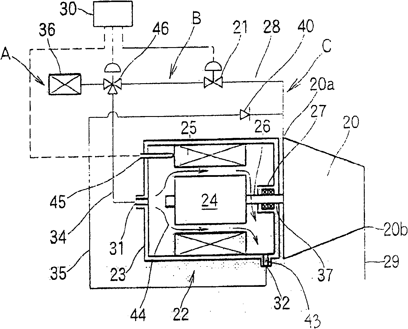
[0016] First, adopt as its cooling system diagram the figure 1 The compressor according to Embodiment 1 of the present invention will be described. This type of compressor has a compressor main body 20, which has a structure in which a pair of male and female screw rotors (not shown) engage and are rotatably accommodated inside a rotor housing. A suction flow path 28 is connected to the suction port 20a of the compressor main body 20, and a discharge flow path 29 is connected to the discharge port 20b. Also, one of the aforementioned pair of male and female screw rotors (usually a male rotor) constituting the compressor main body 20 is connected to a drive shaft 26 of an electric motor 22 .

[0017] By rotating the screw rotor with the motor 22 , the compressor main body 20 compresses the gas supplied from the suction flow path 28 and discharges it into the discharge flow path 29 as high-pressure fluid. The electric motor 22 is composed of a stator 25 fixed to the inner surf...


PUM


Abstract

The invention relates to an effective cooling structure inside the motor that driving the compressor. Wherein, with compressor main body and adsorb channel, said main body is driven by motor; one endof adsorb channel is connected to the inlet of main body; and said compressor has an adsorb adjust valve for adjusting the gas flux of said inlet; the frame of motor is mounted with a gas inlet and agas outlet; via supplying some gas of said adsorb adjust valve to the gas supply channel of frame, the ascending of adsorb adjust valve and the gas inlet are connected; and via feeding the gas of gassupply channel into the gas outlet at the ascending of adsorb adjust valve, the gas outlet and the descending of adsorb adjust valve are connection; therefore, the invention can avoid electric short circuit or rust, without increased cost.

Description

technical field [0001] The present invention relates to a compressor in which oil is supplied to a compressor main body for lubrication and shaft sealing, and more particularly to a cooling structure for a motor driving such a compressor. Background technique [0002] Conventionally, a motor that drives an impeller or a screw rotor of a compressor generates a large amount of heat due to high-speed rotation, so a cooling mechanism is required to cool it. As such a cooling mechanism, forced cooling by a fan directly connected to the rotor shaft, supply of cooling air by an external cooling device, or the like has conventionally been generally used. [0003] However, when the fan is directly connected to the rotor shaft, since the length of the rotor shaft increases, it is difficult to support the rotation of the rotor shaft rotating at high speed, and in the case of supplying cooling air through an external cooling device, other systems are required. The power source or the c...

Claims


Application Information

Patent Timeline
Patent Type & Authority Patents(China)
IPC IPC(8): F04B39/06F04B49/00F04C29/04F04C28/00
Inventor 中村元
Owner 코벨코컴프레서가부시키가이샤
Why Eureka
Try Eureka