Al technical title is built by PatSnap Al team. It summarizes the technical point description of the patent document.
A loader, functional technology, applied to mechanically driven excavators/dredgers, earth movers/shovels, construction, etc., can solve the problems of inconvenient display height and tilt angle adjustment, unfavorable use, etc., to achieve structural Simple, practical, high performance, and easy to use
Active Publication Date: 2018-06-12
义乌市富顺箱包有限公司
View PDF6 Cites 3 Cited by
Summary
Abstract
Description
Claims
Application Information
AI Technical Summary
This helps you quickly interpret patents by identifying the three key elements:
Problems solved by technology
Method used
Benefits of technology
Problems solved by technology
[0003] In the above design, the display screen can display the weight of the material in the bucket. When people watch the display screen, they usually need to adjust the height and inclination angle of the display screen, so that people can better see the conte
Method used
Image
Click on the blue label to locate the original text in one second.
Reading with bidirectional positioning of images and text.
Examples
Embodiment
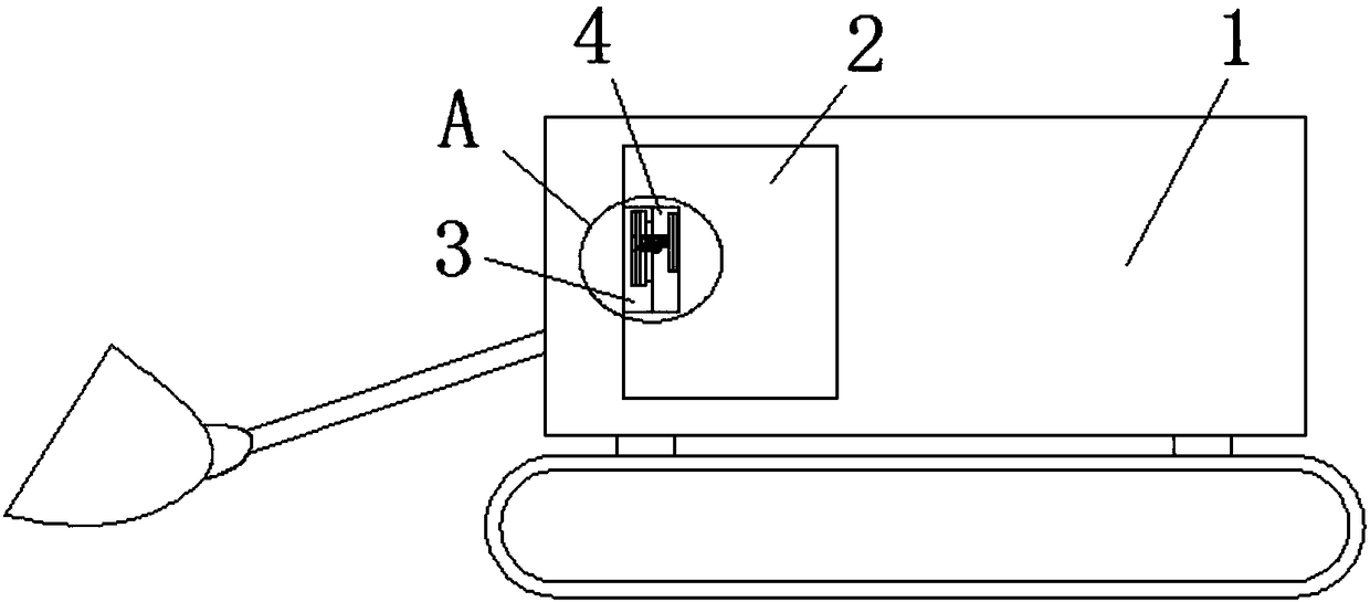
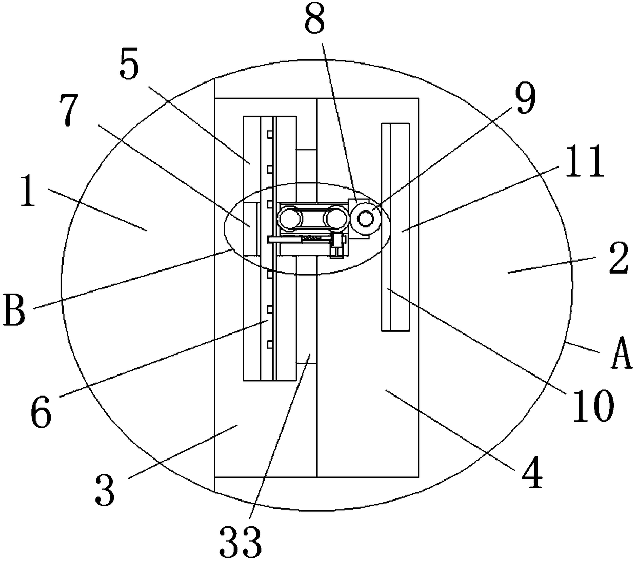
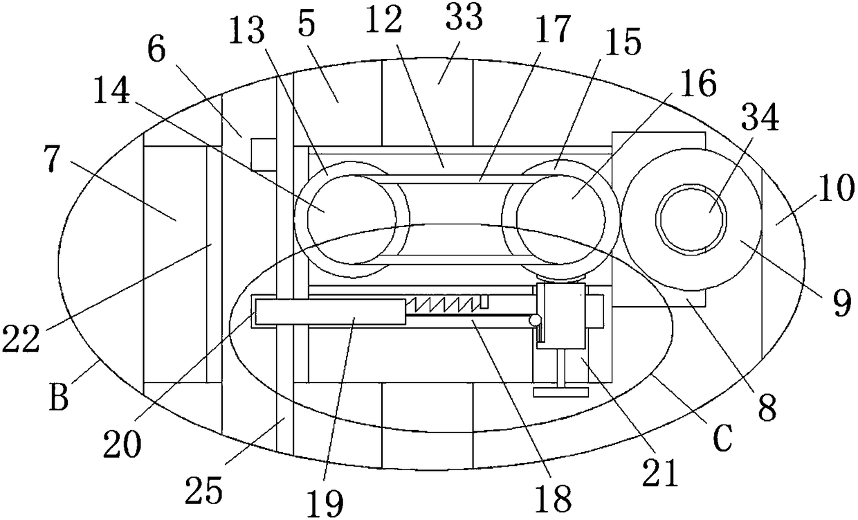
[0027] refer to Figure 1-5, a loader with metering function is proposed in this embodiment, including a loader body 1, a control chamber 2 is provided on the loader body 1, a mounting platform 3 is fixedly installed on one side of the inner wall of the control cavity 2, and the mounting platform The top of 3 is provided with a mounting hole 4 with an opening on one side, and one side of the mounting hole 4 is provided with a cavity 5 on the mounting table 3, and the same limit rod 6 is welded on the top inner wall and the bottom inner wall of the cavity 5 A slide plate 7 is slidably installed on the outside of the limit rod 6, and one side of the slide plate 7 extends into the installation hole 4 and is welded with a rotating plate 8, and one side of the rotating plate 8 is rotatably installed with a first gear 9, the first gear 9 The outside is welded with a mounting plate 10, and the side of the mounting plate 10 away from the slide plate 7 is fixedly equipped with a displa...
PUM
Abstract
The invention discloses a loading machine with a metering function. The loading machine comprises a loading machine body, wherein the loading machine body is provided with a control cavity, and a mounting table is fixedly installed on the inner wall of one side of the control cavity; a mounting hole provided with an opening in one side is formed in the top of the mounting table, one side of the mounting hole is provided with a hollow cavity which is formed in the mounting table, and the inner wall of the top of the hollow cavity and the inner wall of the bottom of the hollow cavity are weldedwith the same limiting rod; a sliding plate is arranged on the outer side of the limiting rod in a sliding mode, one side of the sliding plate extends into the mounting hole and is welded with a rotating plate, and a first gear is rotationally mounted on one side of the rotating plate; a mounting plate is welded to the outer side of the first gear, and the side, away from the sliding plate, of themounting plate is fixedly provided with a display screen; and a limiting hole matched with the limiting rod is formed in the top of the sliding plate, and the limiting rod is in sliding connection with the limiting hole. The loading machine with the metering function is simple in structure and high in practicability, is capable of achieving high adjustment to the display screen and meanwhile capable of adjusting the inclination angle of the display screen, and brings convenience to use by people.
Description
technical field [0001] The invention relates to the technical field of loaders, in particular to a loader with a metering function. Background technique [0002] Loader is a kind of earth and stone construction machinery widely used in construction projects such as roads, railways, construction, hydropower, ports, mines, etc. It is mainly used for shoveling bulk materials such as soil, sand, lime, coal, etc. For light shoveling operations in hard soil, etc., due to the advantages of fast operation speed, high efficiency, good maneuverability, and easy operation, the loader has become one of the main models of earth and stone construction in engineering construction. After retrieval, application for publication The patent document No. CN106088176A discloses a loader with a meter, which design includes a bucket, a moment arm, a loader body and a meter, the loader body is movably connected to the moment arm, and the bucket is connected to the meter The force arm is movably con...
Claims
Application Information
Patent Timeline
Application Date:The date an application was filed.
Publication Date:The date a patent or application was officially published.
First Publication Date:The earliest publication date of a patent with the same application number.
Issue Date:Publication date of the patent grant document.
PCT Entry Date:The Entry date of PCT National Phase.
Estimated Expiry Date:The statutory expiry date of a patent right according to the Patent Law, and it is the longest term of protection that the patent right can achieve without the termination of the patent right due to other reasons(Term extension factor has been taken into account ).
Invalid Date:Actual expiry date is based on effective date or publication date of legal transaction data of invalid patent.