Time synchronization method and apparatus

A technology for time synchronization and information synchronization, which is applied in the Internet field and can solve problems such as poor time synchronization accuracy.

Active Publication Date: 2018-07-10
CHINA MOBILE COMM LTD RES INST +1
View PDF4 Cites 2 Cited by
  • Summary
  • Abstract
  • Description
  • Claims
  • Application Information

AI Technical Summary

Problems solved by technology

[0004] Embodiments of the present invention provide a time synchronization metho

Method used


Image

  • Time synchronization method and apparatus
  • Time synchronization method and apparatus
  • Time synchronization method and apparatus

Examples


no. 1 example

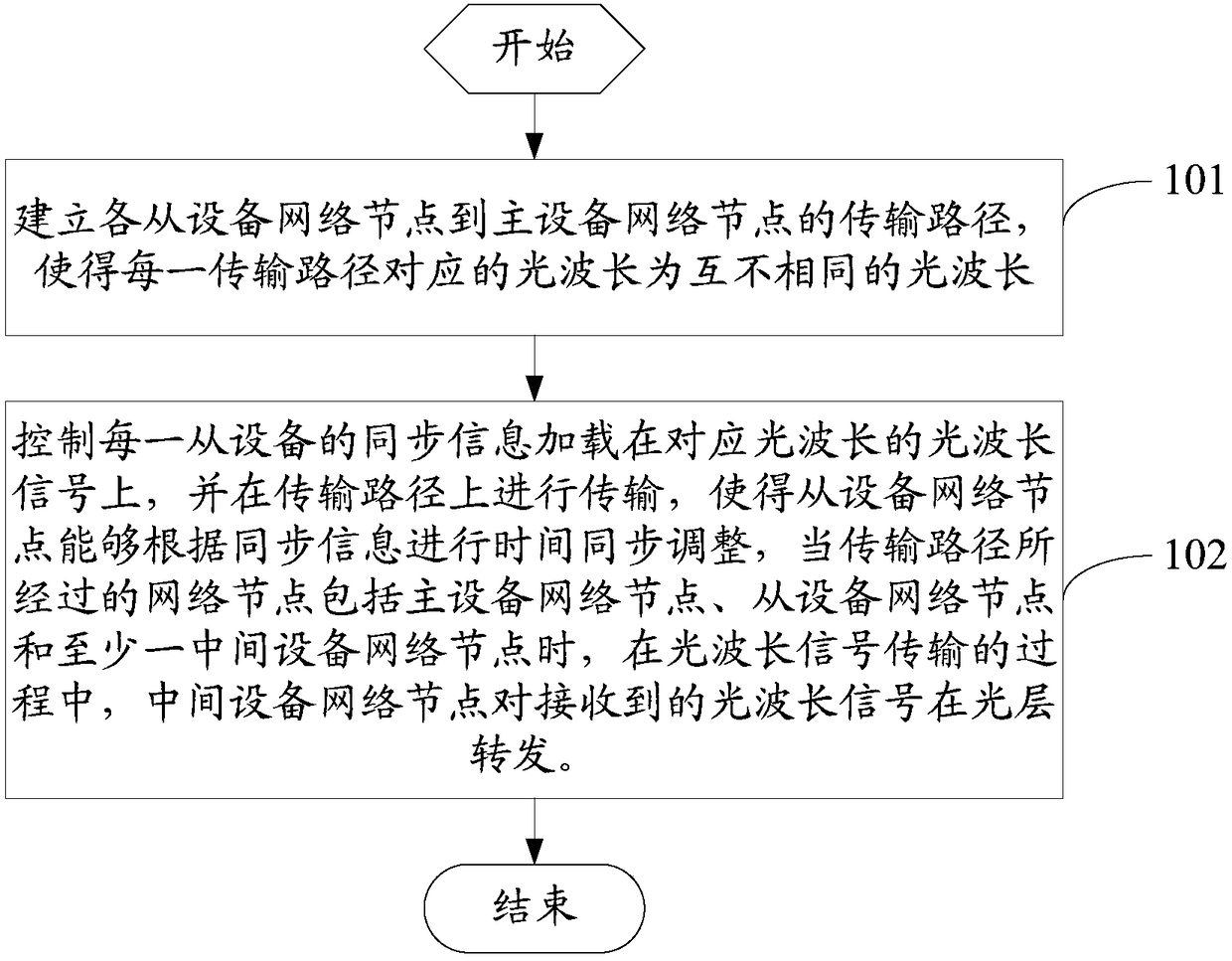
[0034] see figure 1 , figure 1 is a flowchart of a time synchronization method provided by an embodiment of the present invention, and the time synchronization method is applied in a synchronous transmission network, such as figure 1 shown, including the following steps:

[0035] Step 101, establishing transmission paths from each slave device network node to the master device network node, so that the optical wavelengths corresponding to each of the transmission paths are different optical wavelengths;

[0036] The time synchronization method provided in this embodiment is mainly applied in a synchronous transmission network, and is used to perform time synchronization for each network node in the synchronous transmission network.

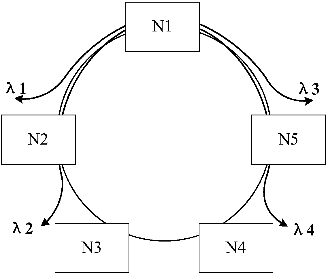
[0037] Specifically, the above-mentioned master device network node may be a node in the middle of the synchronous transmission network, or may be a time reference source device; the above-mentioned slave device network node may be any node in t...

no. 2 example

[0066] see Figure 7 , Figure 7 is a flowchart of a time synchronization method provided by an embodiment of the present invention, and the time synchronization method is applied in a second device network node of a synchronous transmission network, such as Figure 7 shown, including the following steps:

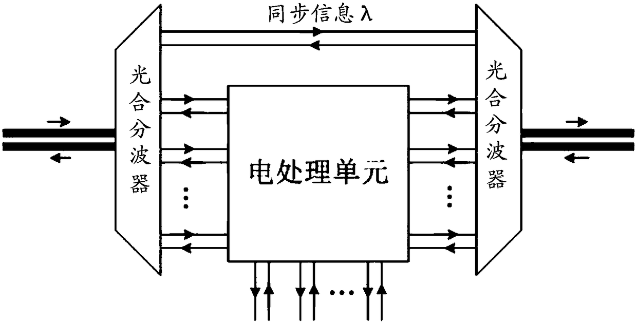
[0067] Step 701: Receive an optical wavelength signal carrying synchronization information sent by the master network node, the optical wavelength signal is a signal transmitted by the transmission path from the master network node to the second device network node, and the transmission path has an independent light wavelength;

[0068] Step 702, when the second device network node is an end node of the transmission path, perform time synchronization adjustment according to the synchronization information;

[0069] Step 703: When the second device network node is an intermediate device network node of the transmission path, control the forwarding of the optical wavelengt...

no. 3 example

[0081] see Figure 8 , Figure 8 It is a structural diagram of a time synchronization device provided by the implementation of the present invention. The time synchronization device is applied in a synchronous transmission network, can realize the details of the time synchronization method in the first embodiment, and achieve the same effect. Such as Figure 8 As shown, the time synchronization device 800 includes a path establishment module 801 and a control module 802, wherein:

[0082] Path establishment module 801, configured to establish transmission paths from each slave device network node to the master device network node, so that the optical wavelengths corresponding to each of the transmission paths are different optical wavelengths;

[0083] The control module 802 is configured to control the synchronization information of each slave device network node to be loaded on the optical wavelength signal corresponding to the optical wavelength, and to transmit on the tr...


PUM


Abstract

The invention provides a time synchronization method and apparatus. The method comprises the following steps: establishing a transmission path from each slave device network node to a master device network node, so that optical wavelengths corresponding to each transmission path are mutually different optical wavelengths; and controlling to load the synchronization information of each slave devicenetwork node on an optical wavelength signal of the corresponding optical wavelength, and transmitting the optical wavelength signal on the transmission path, wherein when the network nodes by whichthe transmission path passes comprise the master device network node, the slave device network nodes and at least one intermediate device network node, in a transmission process of the optical wavelength signal, the intermediate device network node forwards the received optical wavelength signal on an optical layer. As the intermediate device network node of the transmission path does not need toperform photoelectric conversion processing when receiving the optical wavelength signal carrying the synchronization information and directly forwards the optical wavelength signal on the optical layer, a time error imported by the intermediate device network node by performing the photoelectric conversion processing on the optical wavelength signal can be avoided.

Description

technical field [0001] The invention relates to the technical field of the Internet, in particular to a time synchronization method and device. Background technique [0002] TD-SCDMA, CDMA2000, TD-LTE and other mobile communication systems have time synchronization requirements, and the base stations need to meet microsecond-level time synchronization, otherwise, it will cause base station interference and call connections cannot be established. In order to solve the problem of time synchronization, the high-precision time synchronization network sets up a time server upstream, and transmits time information step by step through intermediate nodes, and distributes time information to end base stations. The time transfer protocol usually adopts the IEEE PTP (Precise Time Synchronization) protocol. [0003] In the prior art, when the synchronization network is processed by intermediate nodes at each level, the intermediate nodes extract the time synchronization message, proce...

Claims


Application Information

Patent Timeline
IPC IPC(8): H04J3/06H04J14/02
CPCH04J3/0638H04J3/0667H04J14/0201H04J14/0263
Inventor 韩柳燕
Owner CHINA MOBILE COMM LTD RES INST
Why Eureka
Try Eureka