

Arc-resistant constant voltage static contact group, movable contact group and movable and static contact group for electric switch machine
A technology of static contact and switch machine, which is used in electrical equipment for manipulating turnouts or line circuit breakers, railway car body parts, railway signals and safety, etc., can solve the problem of easy arcing and other problems when the dynamic and static contacts are inserted or pulled out. , to achieve the effect of improving equipment safety and reducing arcing
- Summary
- Abstract
- Description
- Claims
- Application Information
AI Technical Summary
Problems solved by technology
Method used
Image

Examples
Embodiment 1
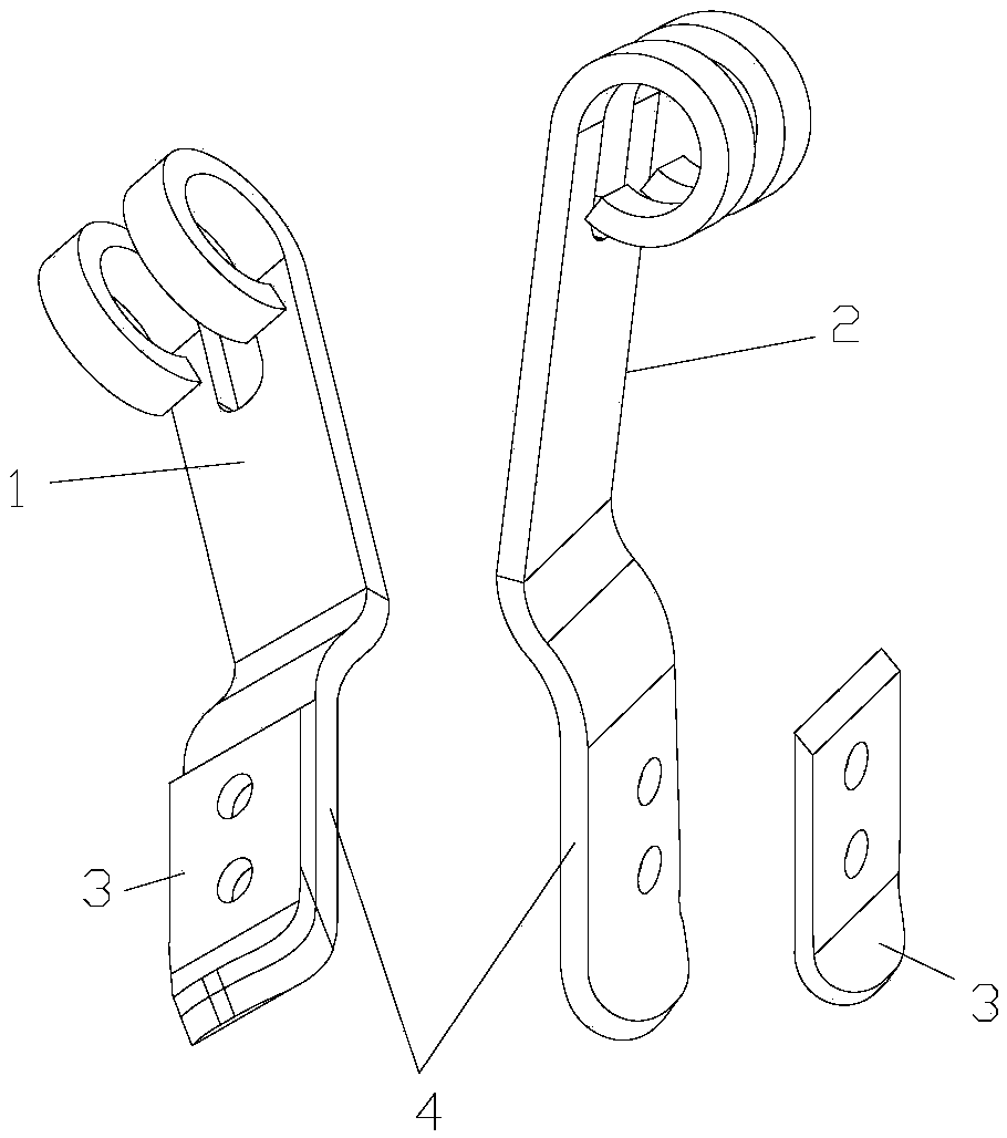
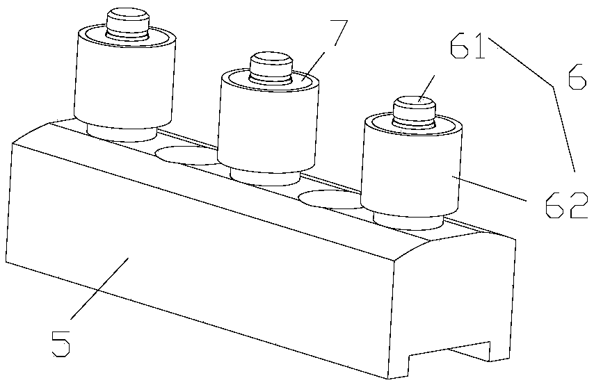
[0039] Such as image 3 and Figure 4 As shown, the magnetic body 7 of the moving contact group is a magnetic ring, and the magnetic ring is arranged on the inner or outer side wall of the moving contact 6 by bonding, riveting, bolting or inlaying, and the height of the magnetic ring is not greater than the height of the moving contact 6 . The specific setting position of the magnetic ring can be selected according to the actual situation.
[0040] Such as Figure 5 and Figure 8 As shown, the moving contact 6 includes a fixed shaft 61 and a moving contact ring 62 movably sleeved on the fixed shaft 61. One end of the fixed shaft 61 is connected to the base body 5, and the magnetic ring is connected to the inner cavity of the moving contact ring 62 with an interference fit. Such as Figure 9 As shown, the inner diameter of the magnetic ring is larger than that of the fixed shaft 61 , and the magnetic ring and the movable contact ring 62 can rotate relative to the fixed shaft ...
Embodiment 2
[0043] The number of magnetic rings is at least one, and two adjacent magnetic rings are connected or spaced, such as Figure 6 As shown, the difference between embodiment 1 and embodiment 2 is that the number of magnetic rings is two, and the two magnetic rings are respectively arranged on the upper and lower parts of the moving contact 6, and the magnetic properties of the upper and lower parts of the two magnetic rings are the same. , that is, when the upper part of the magnetic ring is an N pole, all the upper parts of the magnetic ring are N poles.
Embodiment 3
[0045] Such as Figure 7 As shown, the difference between Embodiment 3 and Embodiment 2 is that an odd number of spiral grooves 621 are uniformly arranged on the outer circumference of the moving contact ring 62, and the two ends of each groove are respectively located on the upper surface of the moving contact ring 62. Along and down, and the top and bottom of two adjacent grooves are on a straight line. Through the setting of the groove, when the movable contact ring 62 is inserted or pulled out between the left and right contact pieces, since the contact area with the left and right contact pieces is different, the friction force between the left and right contact pieces is different. When the contact 6 is activated, the movable contact ring 62 can rotate, so that the friction part of the movable contact ring 62 is different from that of the left and right contact pieces each time, so as to avoid excessive local wear caused by the same friction part when inserting or pullin...
PUM
 Abstract
Description
Claims
Application Information