Multi-layer optical recording device

A technology of optical recording and differential optics, which is applied to optical recording media, optical recording/reproduction, magnetic recording, etc., and can solve the problems of complex reproducing devices and single laser diodes

Inactive Publication Date: 2002-05-29
SAMSUNG ELECTRONICS CO LTD
View PDF2 Cites 0 Cited by
  • Summary
  • Abstract
  • Description
  • Claims
  • Application Information

AI Technical Summary

Problems solved by technology

However, when reading the information of a certain layer, it is necessary to use light with a wavelength different from that of another light for reading another...

Method used


Image

  • Multi-layer optical recording device
  • Multi-layer optical recording device
  • Multi-layer optical recording device

Examples


Embodiment Construction

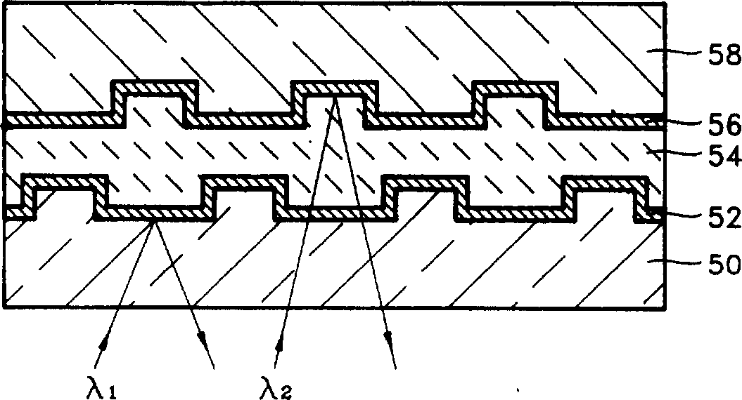
[0023] Figure 4 is a schematic diagram of a multilayer optical recording device according to an embodiment of the present invention.

[0024] Optical disc structure according to the present invention comprises: a transparent substrate 100 that is made by the transparent resin such as PC material by conventional method, a first reflective film 102 that forms on this transparent substrate, a first reflective film of adhering 102 to the adhesion layer 104 of the second reflection film 106, the second reflection film 106 adhered to the first reflection film through the adhesion layer 104, and a protective film 108 formed on the second reflection film 106. The first reflective film 102 adjacent to the transparent substrate 100 is composed of two layers, both of which are preferably composed of dielectric materials. The first dielectric layer a and the second dielectric layer b near the transparent substrate 100 have different refractive indices, and the refractive index of the fir...


PUM


Abstract

A multi-layer optical recording medium having a plurality of reflecting films having different optical reflecting characteristics from each other. The first film is formed of two layers which have a large difference of refractive indices. With such a dielectric being used as a first reflecting film, the reflectivity of the first reflecting film is increased, the structure is simple and a multi-layer optical disk with increased storage capacity can be obtained.

Description

technical field [0001] The present invention relates to a multilayer optical recording device, such as a video disk or a compact disk. More specifically, it relates to a multilayer optical recording apparatus having a multilayer optical disc structure in which the reflectance of a first reflective layer is improved. Background technique [0002] FIG. 1 is a schematic diagram showing the structure of a conventional optical disc. A conventional optical disk is made of a transparent resin material such as polymethyl methacrylate (PMMA) or polycarbonate (PC) and has a laminated structure comprising a transparent substrate 10 with a predetermined pit pattern, a A reflective film 12 is formed by depositing a metal on the transparent substrate 10 by an evaporation method such as sputtering, and a protective film 14 is formed on the reflective film 12 . Here, the reflective film 12 has the same shape as the pit shape of the transparent substrate 10 . [0003] From the above struc...

Claims


Application Information

Patent Timeline
IPC IPC(8): G11B5/62B32B3/00B32B7/023G11B7/24G11B7/2533G11B7/2534G11B7/254G11B7/257G11B7/258
CPCG11B7/24G11B7/2534G11B7/256G11B7/257G11B7/258G11B7/254B32B3/00G11B7/2533Y10S428/913Y10S430/146Y10T428/21Y10T428/31678B32B7/023G11B5/62B32B2429/02B32B7/12B32B2307/416B32B2307/204
Inventor 申世均
Owner SAMSUNG ELECTRONICS CO LTD
Why Eureka
Try Eureka