Centrifugal high-rise escape device and working method thereof

A technology of escape device and working method, applied in life-saving equipment, building rescue, etc., can solve problems such as leakage of hydraulic damping system, difficulty in achieving uniform descent, difficulty in controlling the size of frictional resistance, etc., and achieve the effect of ensuring human safety

Active Publication Date: 2020-10-16
NANTONG VOCATIONAL COLLEGE
View PDF5 Cites 0 Cited by
  • Summary
  • Abstract
  • Description
  • Claims
  • Application Information

AI Technical Summary

Problems solved by technology

[0002] With the increasing number of high-rise buildings in cities and the gradual increase in people's awareness of disaster prevention, high-rise escape devices have gradually become necessary equipment for urban high-rise residents. At present, there are mainly three types of high-rise escape devices: (1) Liquid damping slow The descending lifeguard uses the damping of the liquid flow to convert the potential energy of the load into heat energy to achieve slow descent. The disadvantage is that the hydraulic damping system may leak and a pressure source needs to be provided; It is a buffer device that uses mechanical friction to generate resistance to brake. The disadvantages are: it is difficult to control the size of friction resistance, and it is difficult to achieve a uniform descent; (3) The electromagnetic damping type slow-down lifesaving device uses electromagnetic induction and magnetic field to The way that the current generates force uses electronic technology to realize the automatic control of the life preserver. The disadvantage is that the human body cannot make the generator generate power for the control system to work at the beginning, and the manufacturing cost of the equipment is also relatively high.

Method used


Image

  • Centrifugal high-rise escape device and working method thereof
  • Centrifugal high-rise escape device and working method thereof
  • Centrifugal high-rise escape device and working method thereof

Examples


Embodiment Construction

[0051] In order to make the technical problems, technical solutions and advantages to be solved by the present invention clearer, the following will describe in detail with reference to the drawings and specific embodiments.

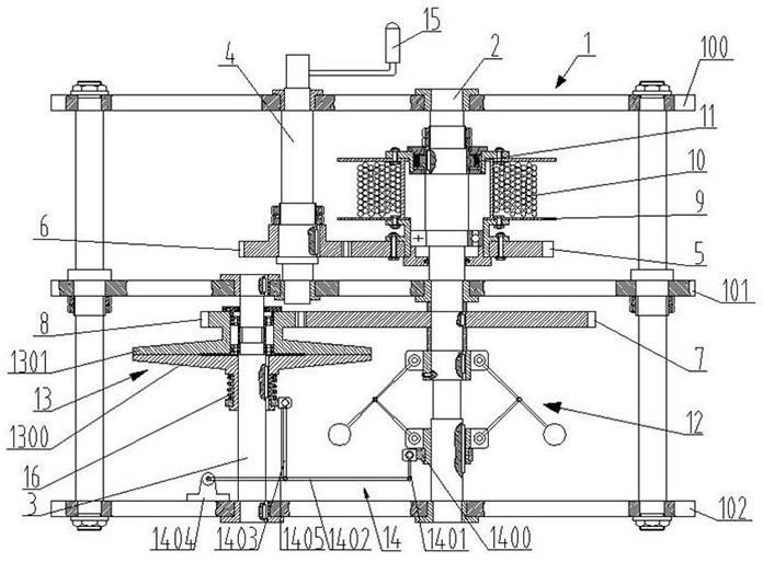
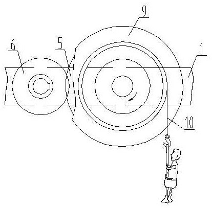
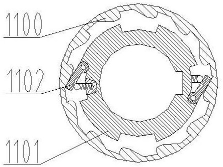
[0052] like figure 1 As shown, a centrifugal high-rise escape device includes a bracket 1, a shaft 2, a shaft 2 3, a shaft 3 4, a gear 5, a gear 2 6, a gear 3 7, a gear 4 8, a reel 9, a wire rope 10, Ratchet mechanism 11, centrifugal speed regulating mechanism 12, friction disc mechanism 13 and lever drive mechanism 14, wherein,

[0053] The two ends of the first axis 2, the second axis 3 and the third axis 4 are respectively supported and positioned on the bracket 1, and the first axis 2, the second axis 3 and the third axis 4 are arranged in parallel, and the third axis 4 is arranged in the radial direction The top is located between axis one 2 and axis two 3 .

[0054] In the present embodiment, the support 1 includes a support plate 100, a support ...


PUM


Abstract

The invention provides a centrifugal high-rise escape device and a working method thereof. The centrifugal high-rise escape device comprises a support, a first shaft, a second shaft, a third shaft, afirst gear, a second gear, a third gear, a fourth gear, a winding drum, a steel wire rope, a ratchet mechanism, a centrifugal speed regulating mechanism, a friction disc mechanism and a lever drivingmechanism; and the centrifugal speed regulating mechanism comprises a centrifugal seat, a centrifugal rod, a flying ball, a shaft ring and a connecting rod, wherein one end of the centrifugal rod is hinged to the centrifugal seat, the other end of the centrifugal rod is fixedly connected with the flying ball, the shaft ring is coaxially arranged on the first shaft in a sliding mode, and the two ends of the connecting rod are hinged to the shaft ring and the centrifugal rod correspondingly. According to the centrifugal high-rise escape device, the centrifugal speed regulating mechanism and thefriction disc mechanism are innovatively adopted, the axial driving force to a fixed friction disc is generated by utilizing the centrifugal speed regulating mechanism, the axial driving force is amplified through the lever driving mechanism, and a compression spring is used for adjusting displacement and transmitting the axial driving force to the fixed friction disc, so that the friction resistance moment is promoted to be generated between the fixed friction disc and a movable friction disc, and a human body can be prevented from falling down rapidly.

Description

technical field [0001] The invention belongs to the technical field of safety escape equipment, and in particular relates to a centrifugal high-rise escape device and a working method thereof. Background technique [0002] With the increasing number of high-rise buildings in cities and the gradual increase in people's awareness of disaster prevention, high-rise escape devices have gradually become necessary equipment for urban high-rise residents. At present, there are mainly three types of high-rise escape devices: (1) Liquid damping slow The descending lifeguard uses the damping of the liquid flow to convert the potential energy of the load into heat energy to achieve slow descent. The disadvantage is that the hydraulic damping system may leak and a pressure source needs to be provided; It is a buffer device that uses mechanical friction to generate resistance to brake. The disadvantages are: it is difficult to control the size of friction resistance, and it is difficult t...

Claims


Application Information

Patent Timeline
Patent Type & Authority Patents(China)
IPC IPC(8): A62B1/12
CPCA62B1/12
Inventor 张丽萍李业农
Owner NANTONG VOCATIONAL COLLEGE
Why Eureka
Try Eureka