
Lifter oil pipe burst safety mechanism
A technology of safety mechanism and lift, which is applied in the direction of hoisting equipment safety devices, lifting frames, lifting devices, etc., can solve the problems of operator injury, sudden burst, equipment damage, etc., and achieve the effect of improving the safety factor
- Summary
- Abstract
- Description
- Claims
- Application Information
AI Technical Summary
Problems solved by technology
Method used
Image

Examples
Embodiment Construction
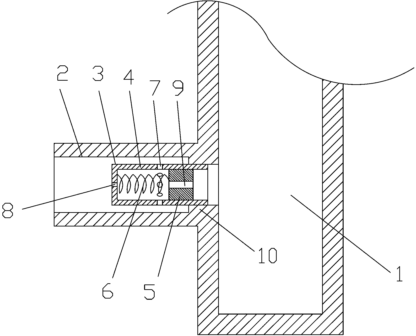
[0010] The lift oil pipe burst safety mechanism of the present invention, such as figure 1 As shown, it includes an explosion-proof flow valve 3 installed in the oil inlet pipe 2 provided by the hydraulic cylinder 1 of the lift. The hydraulic cylinder 1 provides lifting power for the lift. The explosion-proof flow valve 3 includes a barrel-shaped valve body 4 And the valve core 5, the inner end of the oil inlet pipe 2 is provided with a step 10 whose inner diameter is smaller than the oil inlet pipe 2, and the inner end of the valve body 4 is installed on the step 10.
[0011] The inner end of the valve body 4 is open, and the valve core 5 is slidingly installed in the valve body 4. The inner cavity of the valve body 4 outside the valve core 5 is a buffer cavity. The middle part of the side wall of the valve body 4 is provided with a plurality of main oil seepage holes 7, the outer end of the valve body 4 is provided with a secondary oil seepage hole 8, and the valve core 5 is...
PUM
 Abstract
Description
Claims
Application Information