Concrete stirrer

A mixer and concrete technology, applied in cement mixing devices, clay preparation devices, chemical instruments and methods, etc., can solve the problems of a single fixed rotating mixing method, low mixing efficiency, and not easy to carry, etc. The effect of reducing efficiency

Active Publication Date: 2018-12-11
天门市天安建材有限公司
View PDF10 Cites 5 Cited by
  • Summary
  • Abstract
  • Description
  • Claims
  • Application Information

AI Technical Summary

Problems solved by technology

[0002] Concrete mixer is a commonly used material processing device on construction sites. Inside the concrete mixer, the drive motor is used to drive the mixing shaft and the mixing blades installed on the mixing shaft to rotate, and the mixing blades are used to stir. There are many deficiencies in the above structure, such as: mixing blades and mixing The shaft is welded and fixed, so it i

Method used


Image

  • Concrete stirrer
  • Concrete stirrer
  • Concrete stirrer

Examples


Embodiment Construction

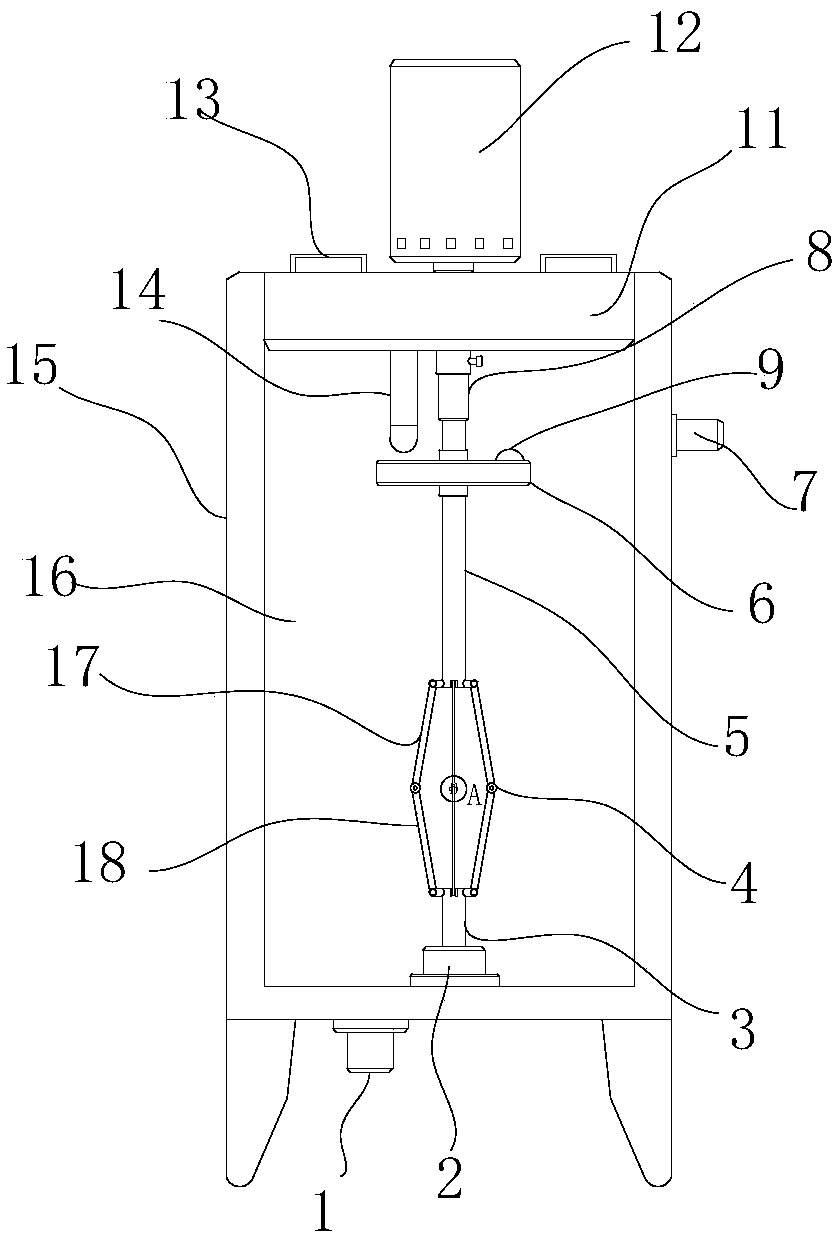
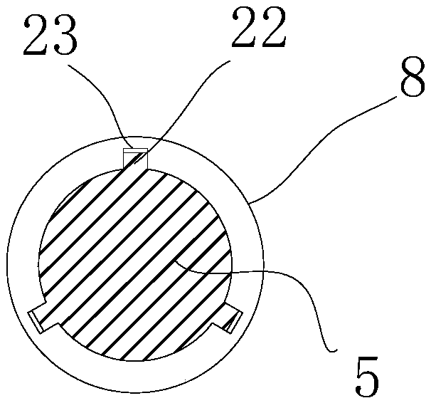
[0020] Such as figure 1 As shown, the concrete mixer includes a mixer shell 15, the upper end of the mixer shell 15 is open, the inner wall of the opening end is provided with an internal thread, and the opening end is threaded into a rotating cover 11, and the outer wall of the rotating cover 11 is engaged with the internal thread of the opening end. , a driving motor 12 is installed on the top of the rotating cover 11, and the motor shaft of the driving motor 12 is connected to a connecting rod 8 by a coupling, and a first rotating rod 5 is telescopically loaded into the connecting rod 8, and the first rotating rod 5 The top is telescopically loaded into the connecting rod 8;

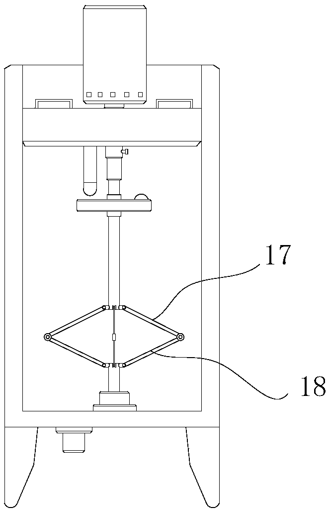
[0021] The bottom of the first rotating rod 5 is provided with more than one first stirring blade 17 around the first rotating rod 5, and the other side of the first stirring blade 17 passes through the hinged structure 4 (such as Figure 4 shown) is hinged to a second stirring piece 18, the other en...


PUM


Abstract

The invention discloses a concrete stirrer. The concrete stirrer comprises a stirring shell, wherein the upper end face of the stirring shell is open; the inner wall of the opening end is provided with an internal thread; a rotating cover is arranged in the opening end in a threaded manner; the outer wall of the rotating cover is in threaded engagement with the internal thread of the opening end;a driving motor is arranged on the top of the rotating cover; a motor shaft of the driving motor is connected with a connecting rod through a coupler; a first rotating rod is arranged in the connecting rod in a telescopic manner; the top of the first rotating rod is arranged in the connecting rod in a telescopic manner; the bottom of the first rotating rod is provided with one or above first stirring blades around the first rotating rod. By adopting the concrete stirrer, the included angle between a first stirring blade and a second stirring blade can be adjusted by means of the height of therotating cover relative to the stirring shell in order to adjust the stirring width of the whole stirring blade, and lifting type opening-closing stirring can be realized during stirring, so that thestirring efficiency is improved greatly. When not being in use, the whole stirring rod is in a beeline form, so that the concrete stirrer is convenient to carry and clean.

Description

technical field [0001] The invention relates to the construction field, in particular to a concrete mixer. Background technique [0002] Concrete mixer is a commonly used material processing device on construction sites. Inside the concrete mixer, the drive motor is used to drive the mixing shaft and the mixing blades installed on the mixing shaft to rotate, and the mixing blades are used to stir. There are many deficiencies in the above structure, such as: mixing blades and mixing The shaft is welded and fixed, so it is bulky and not easy to carry. Because of its irregular shape, it is very inconvenient to clean; moreover, the length of the stirring blade is fixed. When stirring, the radius of stirring has been determined, and post-control adjustment cannot be performed. , and there is only a single fixed rotation stirring mode, so the stirring efficiency is low, and there are many deficiencies in its use. Contents of the invention [0003] The technical problem to be so...

Claims


Application Information

Patent Timeline
IPC IPC(8): B28C5/16
CPCB28C5/16
Inventor 杜天阳
Owner 天门市天安建材有限公司
Why Eureka
Try Eureka