Polygonal self-balancing type vibration exciter for concrete mixing equipment

A mixing equipment and self-balancing technology, which is applied in the field of polygonal self-balancing vibrator, can solve the problems affecting the health of construction workers, the force of the vibrator is not easy to balance, and the sealing effect of the shaft end is not good, so as to achieve macroscopic and Microscopic uniformity, improved mixing quality and efficiency, and simple structure

Pending Publication Date: 2018-03-02
CHANGAN UNIV
View PDF7 Cites 0 Cited by
  • Summary
  • Abstract
  • Description
  • Claims
  • Application Information

AI Technical Summary

Problems solved by technology

The exciter of the existing vibrating mixer adopts the principle of eccentricity to generate vibration, the sealing effect of the shaft end is not good, and the stress state of the bearing is not good; it is easy to generate heat under high-frequency vibration state, and the life of the bearing is not high; at the same time, the force is complicated when stirring , the force of the exciter is not easy to balance, the vibration energy cannot all act on the work object and it is easy to generate noise pollution, which makes the site construction conditions harsh, does not meet the current environmental protection requirements of our country, and even affects the health of construction workers

Method used


Image

  • Polygonal self-balancing type vibration exciter for concrete mixing equipment
  • Polygonal self-balancing type vibration exciter for concrete mixing equipment
  • Polygonal self-balancing type vibration exciter for concrete mixing equipment

Examples


Embodiment Construction

[0019] The present invention will be further described below in conjunction with the drawings:

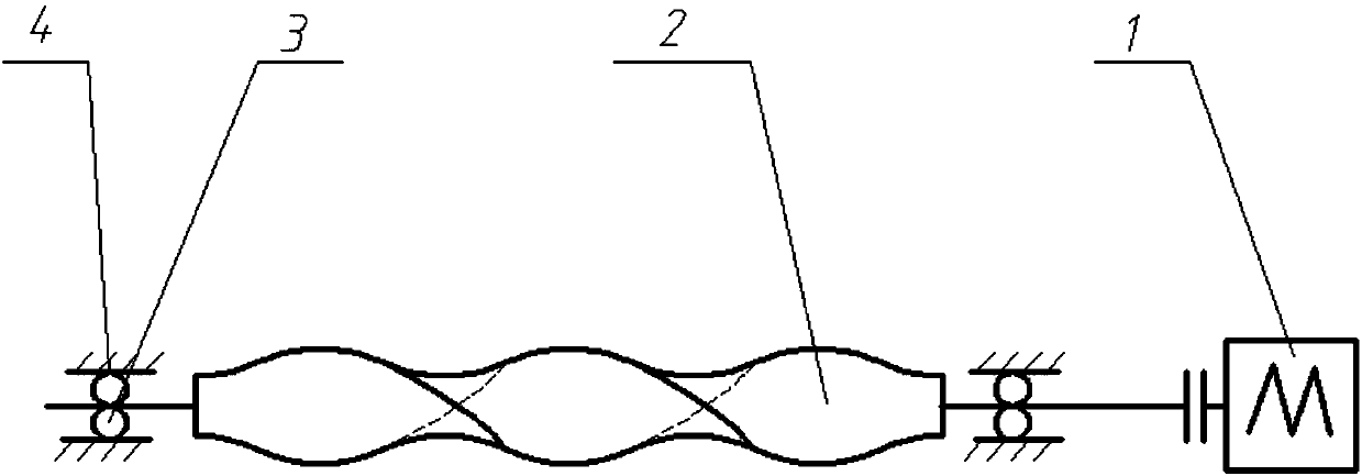
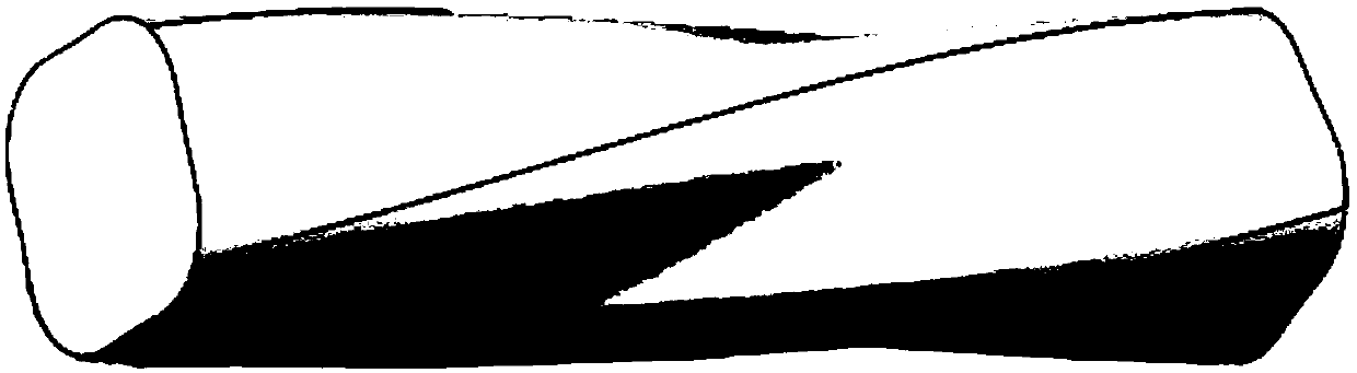
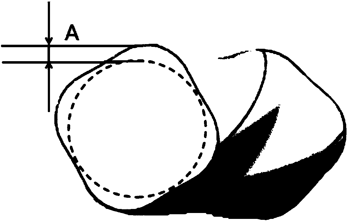
[0020] See Figure 1-Figure 3 , A polygonal self-balancing vibration exciter for concrete mixing equipment, comprising a power device 1, a polygonal vibration shaft 2; two ends or one end of the polygonal vibration shaft 2 are provided with a power device 1, and the power device 1 drives the polygonal vibration shaft 2 to rotate The polygonal vibrating shaft 2 is a polygonal shaft with N smooth and convex cross-sections, where N is greater than or equal to 1; the smooth convexes are arranged spirally along the axis of the polygonal vibrating shaft 2.

[0021] The two ends or one end of the polygonal vibrating shaft 2 are provided with a connecting shaft, a bearing 3 is sleeved on the connecting shaft, and the output end of the power device 1 is connected with the connecting shaft.

[0022] A frame 4 is provided on the bearing 3.

[0023] The helix angle of the polygonal vibration shaft 2 ...


PUM

PropertyMeasurementUnit
angleaaaaaaaaaa

Abstract

A polygonal self-balancing type vibration exciter for concrete mixing equipment comprises one or two power devices and a polygonal vibration shaft; the one or two power devices are arranged at one ortwo ends of the polygonal vibration shaft and drive the polygonal vibration shaft to rotate; the polygonal vibration shaft is a polygonal shaft with the cross section having N smooth bulges, and N islarger than or equal to 1; and the smooth bulges are arranged spirally in the axial direction of the polygonal vibration shaft. The polygonal vibration shaft is a solid shaft or a hollow shaft, and the mass center of the polygonal vibration shaft is overlapped with the rotating center of the polygonal vibration shaft; the vibration excitation frequency of the vibration exciter is in linear positive correlation with the number N of the bulges and can be increased through increase of N or the rotating speed; the amplitude of the vibration excitation force can be adjusted through change of the bulge height, the material movement direction can be changed through change of the lead angle of the polygonal vibration shaft, and different vibration excitation effects can be realized. The vibrationexciter overcomes the defects of an eccentric vibration exciter, vibration mixing is realized under the combined action of the vibration exciter and the mixing equipment, and improvement of the mixingquality and efficiency is facilitated.

Description

Technical field [0001] The invention belongs to the technical field of vibration excitation equipment, and relates to a polygonal self-balancing type vibration exciter for concrete mixing equipment. Background technique [0002] Compared with traditional compulsory mixer, vibration mixing is more and more widely used in engineering applications because of its higher mixing efficiency and good mixing quality. Concrete vibration mixing is to mix the materials through the high frequency vibration generated by the vibration exciter and the mixing device to improve the mixing quality and efficiency. The exciter of the existing vibration mixer adopts the principle of eccentricity to generate vibration, the sealing effect of the shaft end is not good, and the bearing force is not good; it is very easy to heat under high-frequency vibration, and the bearing life is not long; at the same time, the force is complicated when stirring , The force of the vibrator is not easy to balance, the v...

Claims


Application Information

Patent Timeline
Patent Type & Authority Applications(China)
IPC IPC(8): B28C5/08B28C5/48
CPCB28C5/0806B28C5/48
Inventor 姚运仕赵明明杨发冯忠绪沈建军
Owner CHANGAN UNIV
Why Eureka
Try Eureka