A panoramic video monitoring device

A monitoring device and a panoramic video technology, which can be used in closed-circuit television systems and other directions, and can solve problems such as not being able to meet the needs of monitors

Inactive Publication Date: 2019-01-08
湖南众从信息科技有限公司
View PDF0 Cites 2 Cited by
  • Summary
  • Abstract
  • Description
  • Claims
  • Application Information

AI Technical Summary

Problems solved by technology

[0002] Our common video surveillance devices are fixed-mounted cameras on the ceiling. This single-direction and position monitoring device can no longer meet people's needs for monitors.

Method used


Image

  • A panoramic video monitoring device
  • A panoramic video monitoring device

Examples


Embodiment Construction

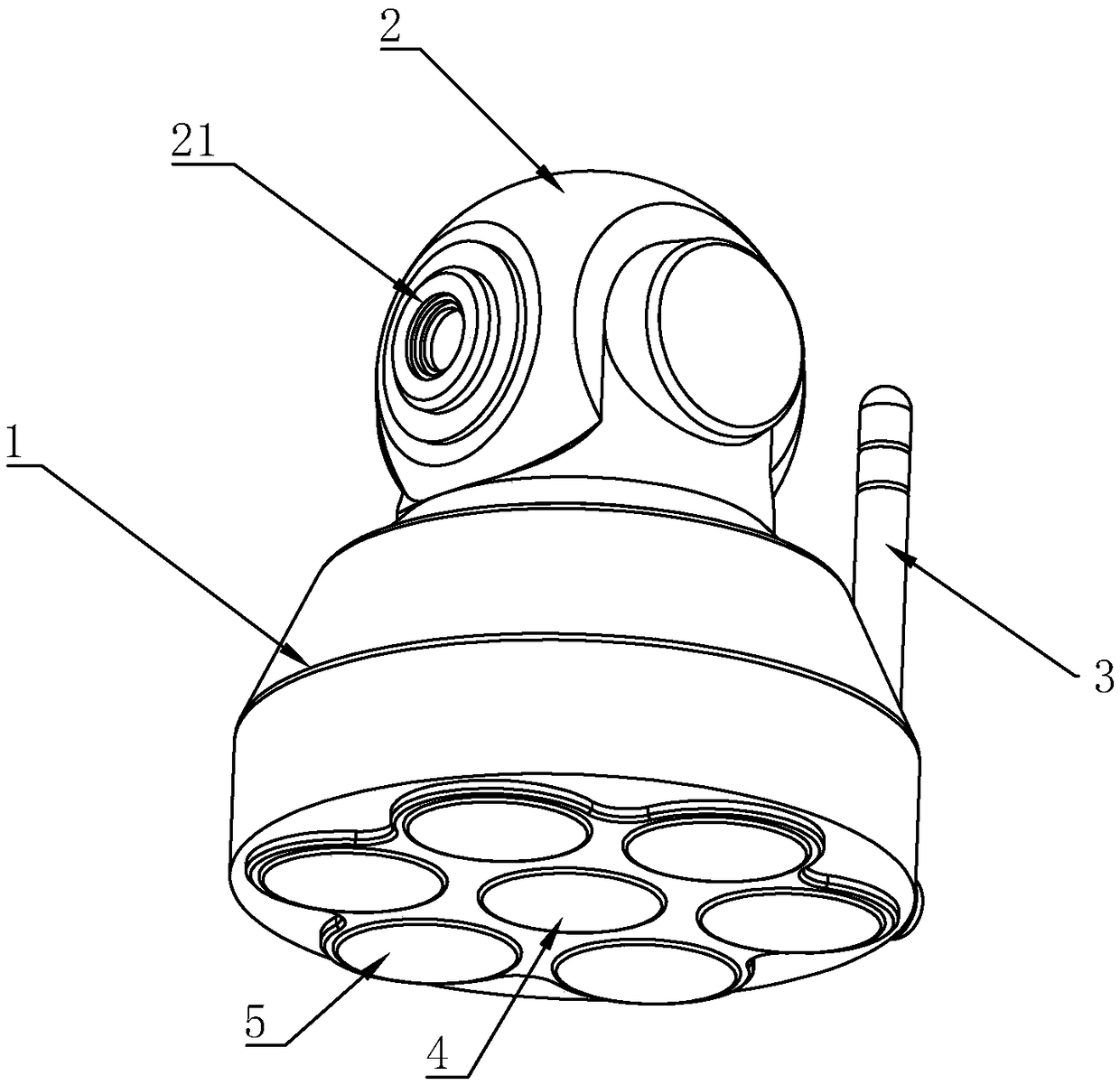
[0015] Such as figure 1 , figure 2 As shown, it is a panoramic video monitoring device of the present invention, including a housing 1, a video monitor 2 and a wireless transmission module 3 installed on the housing 1, and the wireless transmission module 3 is used to capture the video captured by the video monitor 2. The image data is fed back to the background of the monitoring center and receives control instructions from the background;

[0016] On the one hand, in order to realize 360° monitoring without dead angle, the technical solution designs the video monitor 2 as a spherical structure, and 180° cameras 21 are respectively arranged on both sides of the spherical structure, so as to complete the image acquisition within the 360° viewing angle range. The 180 ° camera 21 is all connected with the wireless transmission module 3 to send video data;

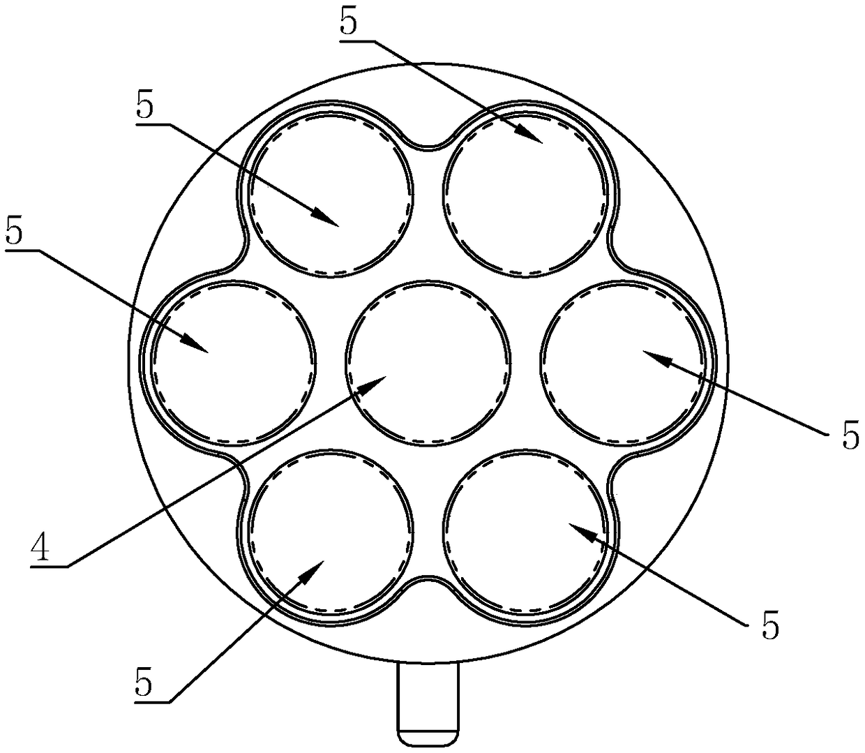
[0017] On the other hand, in order to realize the scene switching of the monitoring area, the bottom of the casing 1 of ...


PUM


Abstract

A panoramic video monitoring device includes a housing and a video monitor and a wireless transmission module mounted on the housing, As that spherical video monitor is respectively provide with two 180-degree cameras, Real-time acquisition of image data in the range of 360 DEG, and six directional driving balls at the bottom of the housing, the polarity of driving balls to drive the movement of the central rolling ball circuit, with the rolling of each ball to achieve 360 direction of arbitrary movement, so that the monitoring area is no longer bound.

Description

technical field [0001] The invention relates to the field of video monitoring, in particular to a panoramic video monitoring device. Background technique [0002] Our common video surveillance devices are cameras fixed on the ceiling. This single-direction and positional surveillance device can no longer meet people's needs for monitors. For example, the monitoring angle needs to be 360° without dead angles, the monitoring area needs to be changeable, and can be flexibly switched according to different time periods. Contents of the invention [0003] In order to solve the above technical problems, the object of the present invention is to provide a panoramic video monitoring device with 360-degree monitoring without dead angle and switchable monitoring areas. [0004] The technical scheme adopted in the present invention is: [0005] A panoramic video monitoring device, comprising a housing, a video monitor and a wireless transmission module installed on the housing, the...

Claims


Application Information

Patent Timeline
Patent Type & Authority Applications(China)
IPC IPC(8): H04N7/18
CPCH04N7/18
Inventor 杨家明
Owner 湖南众从信息科技有限公司
Why Eureka
Try Eureka