A digital proportional-integral-differential compensation circuit based on dual signal path

A compensation circuit and dual-signal technology, which is applied in the direction of electrical components, electric variable adjustment, output power conversion devices, etc., can solve the problems of not being able to adapt to complex control and single control method, and achieve flexible control methods, fewer peripheral devices, Control powerful effects

Active Publication Date: 2019-01-18
UNIV OF ELECTRONICS SCI & TECH OF CHINA
View PDF6 Cites 1 Cited by
  • Summary
  • Abstract
  • Description
  • Claims
  • Application Information

AI Technical Summary

Problems solved by technology

[0005] Aiming at the problem that the above-mentioned analog compensation control method has a single control method and cannot adapt to complex control, the present invention proposes a digital proportional-integral-differential compensation circuit based on dual signal paths. Compared with the analog compensation control method, it can play The advantages of digital signal processors, stronger control functions, short design cycle, flexible control methods, programmability, fewer peripheral devices, advanced correction capabilities, etc.; and only two channels are used, compared with traditional digital compensation The proportional, integral and differential paths used by the circuit reduce the complexity of loop compensation and the number of gate circuits used, especially for DC-DC switching converters

Method used


Image

  • A digital proportional-integral-differential compensation circuit based on dual signal path
  • A digital proportional-integral-differential compensation circuit based on dual signal path
  • A digital proportional-integral-differential compensation circuit based on dual signal path

Examples


Embodiment Construction

[0037] Below in conjunction with accompanying drawing and specific embodiment, describe technical solution of the present invention in detail:

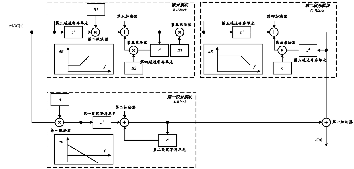
[0038] The present invention adopts the pseudo three-type compensation (PT3) of dual signal paths to realize digital proportional-integral-differential compensation, which is essentially an infinite impulse response filter (IIR filter) structure, such as figure 2As shown, it includes a differential module, a first integral module, a second integral module and a first adder, the input of the first integral module is connected to the input of the differential module and is used as the input of the digital proportional-integral-differential compensation circuit, which The output end is connected to the first input end of the first adder; the input end of the second integral module is connected to the output end of the differential module, and its output end is connected to the second input end of the first adder; the output end of the se...


PUM


Abstract

A digital proportional-integral-differential compensation circuit based on dual signal path belongs to the field of integrated circuit technology. The circuit includes a derivative module, a first integrating module, a second integrating module, and a first adder, wherein an input of the first integrating module is connected to an input of the derivative module and serves as an input ned of a digital proportional-integral-differential compensation circuit, an output terminal of which is connected to a first input terminal of the first adder; An input terminal of the second integrating moduleis connected to an output terminal of the differentiating module, and an output terminal thereof is connected to a second input terminal of the first adder; The output of the first adder is used as the output end of the digital digital proportional-integral-differential compensation circuit. The invention has strong control function compared with the analog compensation control method, Compared with the traditional digital compensation circuit, the control method has the advantages of flexibility, programmability, less peripheral devices and advanced correction ability. Compared with the traditional digital compensation circuit, the control method reduces the complexity of loop compensation and the number of gates used, and improves the circuit bandwidth as well as the circuit gain.

Description

technical field [0001] The invention belongs to the technical field of integrated circuits, and relates to a digital proportional-integral-differential compensation circuit (Digital Proportion Integration Differentiation Compensator, DPID) based on dual signal paths, which can be applied to DC-DC switching converters for digital control compensation. Background technique [0002] In the traditional power electronic power conversion control system, analog PID (ie proportional-integral-derivative) control is the most mature and widely used control method. With the popularization and application of computers in the field of control, digital PID control has been more and more widely used in modern power electronic power conversion control systems. In recent years, as the power management function becomes more and more complex, the requirements for the control part continue to increase, and the switching power supply has entered the digital control stage from analog control and a...

Claims


Application Information

Patent Timeline
Patent Type & Authority Applications(China)
IPC IPC(8): H02M3/158
CPCH02M3/158H02M1/0025
Inventor 甄少伟武昕王佳佳陈思远罗萍张波
Owner UNIV OF ELECTRONICS SCI & TECH OF CHINA
Why Eureka
Try Eureka