Cooking utensil

A technology for cooking utensils and cooking cavities, which is applied to the lids of cooking utensils, cooking utensils, household utensils, etc., can solve the problems of long waiting time for opening the cover and long cooking time, so as to reduce the non-heating waiting time, shorten the cooking time, and speed up the Effects of the cooking process

Pending Publication Date: 2019-02-05
ZHEJIANG SHAOXING SUPOR DOMESTIC ELECTRICAL APPLIANCE CO LTD
View PDF5 Cites 3 Cited by
  • Summary
  • Abstract
  • Description
  • Claims
  • Application Information

AI Technical Summary

Problems solved by technology

[0011] The main purpose of the present invention is to provide a cooking utensil to solve the problem of to

Method used


Image

  • Cooking utensil
  • Cooking utensil
  • Cooking utensil

Examples


Embodiment 1

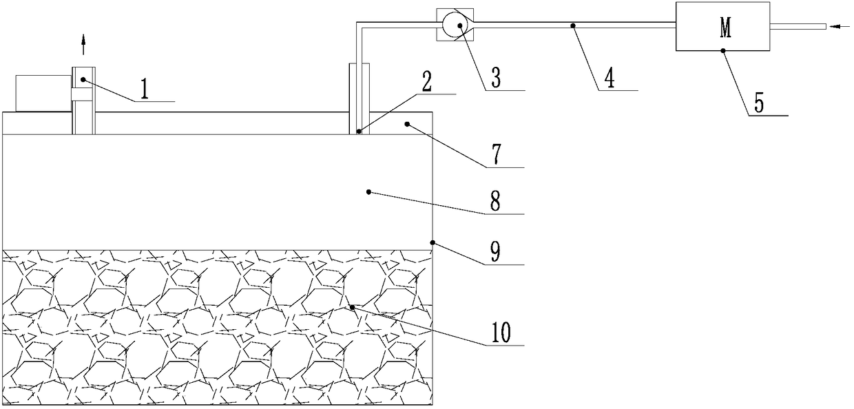
[0053] The cooking utensil of Embodiment 1 is an electric pressure cooker, figure 1 A working schematic diagram of the electric pressure cooker for quick porridge cooking is shown. The cooking utensil of Embodiment 1 includes: an inner pot 9 , a cooking cavity 8 is formed in the inner pot 9 , and ingredients 10 are accommodated in the cooking cavity 8 . The electric pressure cooker also includes an exhaust port 1, a pressure limiting valve, an air inlet 2, a one-way valve 3, an air intake channel 4, an air pump 5, a pot cover 7 and a heating device. The air inlet 2 and the exhaust outlet 1 are all arranged on the pot cover 7 . The heating device is used for heating the cooking cavity. The above pressure limiting valve is also called exhaust valve.

[0054] The air pump 5 is arranged on the air intake channel 4 to suck the air outside the cooking utensil into the cooking cavity. A pressure limiting valve is provided at the exhaust port 1, and the exhaust port 1 communicates...

Embodiment 2

[0067] The working principle of embodiment two is as follows:

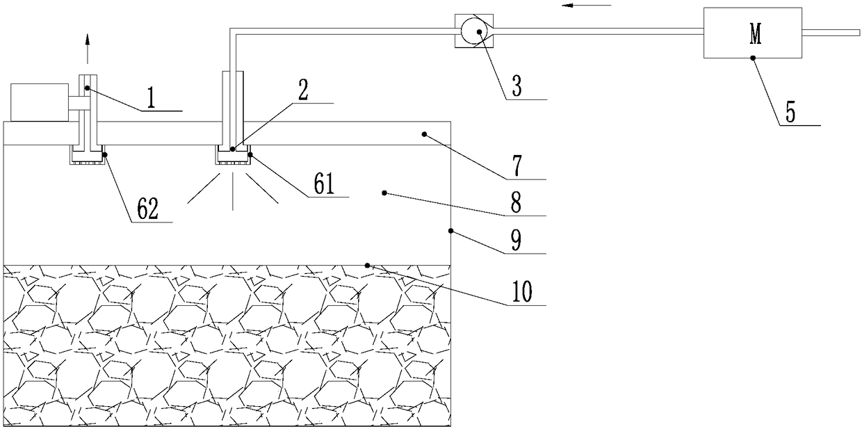
[0068] When the food material 10 is cooked in the closed cooking cavity 8 composed of the pot cover 7 and the inner pot 9, and the air pump 5 adds cold air to the closed cavity through the one-way valve 3, the intake air from the air inlet 2 passes through the air intake cap. 61 disperses and sprays the intake air to the surface of the food material 10 in the inner pot 9, so that the maximum area plays a cooling role and reduces foam generation and overflow. At the same time, during the discharge and cooking process, the foam generated on the surface of the food material 10 is not easy to enter the air inlet 2 and the air outlet 1, which reduces the risk of overflow and facilitates cleaning.

[0069] Since the air intake cap 61 is provided as a guide part at the air inlet, the guide part disperses and / or changes the direction of the airflow at the air inlet, so the guide part can disperse the intake air above the ...

Embodiment 4

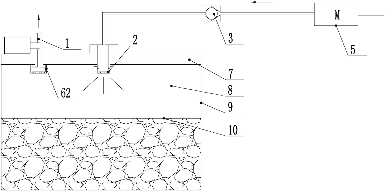
[0074] The cooking utensil of Embodiment 4 is also an electric pressure cooker, which is convenient for frequent disassembly and cleaning of the inner cover of the pot cover 7 . The one-way valve 3 is arranged at the communication place between the air intake channel 4 and the cooking cavity. The one-way valve 3 of the fourth embodiment is set at a detachable position of the inner cover to realize washability and prevent food materials in the inner cavity of the electric pressure cooker from entering the air intake passage 4 .

[0075] The electric pressure cooker of Embodiment 4 includes an inner pot 9 , and a cooking cavity 8 is formed in the inner pot 9 , and ingredients 10 are accommodated in the cooking cavity 8 . The electric pressure cooker also includes an exhaust port 1, an air intake port 2, a one-way valve 3, an air intake passage 4, an air pump 5, an air intake cap 61, an exhaust cap 62 and a pot cover 7. A pressure limiting valve is provided at exhaust port 1.

...


PUM


Abstract

The invention provides a cooking utensil. The cooking utensil comprises a cooking cavity, a heating device, an air inlet channel, an air pump and an exhaust port, wherein the cooking cavity is used for containing food materials, the heating device is used for heating the cooking cavity, the air inlet channel makes the cooking cavity communicated with the outside of the cooking utensil, the air pump is arranged on the air inlet channel so as to pump air outside the cooking utensil into the cooking cavity, and the exhaust port is provided with a pressure limiting valve and communicated with thecooking cavity so as to make gas in the cooking cavity flow out of the cooking utensil; through the air pump, cold air can be pumped into the cooking cavity in the presence of pressure in the cookingcavity, and the cold air is mixed with gas in the cooking cavity and then discharged through the exhaust port. By means of the technical scheme, the problem of overlong overall cooking time or overlong uncovering waiting time in the prior art is effectively solved.

Description

[0001] This application requires that the application date is July 28, 2017, the application number is 201710632451.0, and the priority and application date of the invention patent application titled "Cooking Appliance, Cooking Machine and Cooking Control Method" is December 29, 2017. The priority of the invention patent application with the application number 201711498327.6 and the invention name "cooking utensils". technical field [0002] The invention relates to the field of small household appliances, in particular to a cooking utensil. Background technique [0003] When cooking utensils to cook viscous food such as porridge and porridge, foam and overflow are easily generated. Therefore, during the cooking process, there is a long waiting period during the heating stage. Otherwise, once the pressure rises, there will be a risk of overflowing the pot. This results in an excessively long cooking time. [0004] In view of the above problems, the Chinese invention patent ...

Claims


Application Information

Patent Timeline
IPC IPC(8): A47J27/08A47J27/092A47J36/06A47J36/38
CPCA47J27/00A47J27/004A47J27/08A47J27/0802A47J27/086A47J27/092A47J27/56A47J36/00A47J36/06A47J36/24A47J36/2483A47J36/32A47J36/38
Inventor 吕华
Owner ZHEJIANG SHAOXING SUPOR DOMESTIC ELECTRICAL APPLIANCE CO LTD
Why Eureka
Try Eureka