Electromagnetic heating device, electromagnetic heating system and control method thereof

A heating system and control method technology, applied in the direction of electric heating device, induction heating control, electric/magnetic/electromagnetic heating, etc., can solve problems such as easy heating, small pulse width, excessive IGBT loss, etc., to prevent heating and burning, suppress Pulse current, effect of improving reliability

Active Publication Date: 2021-06-18
FOSHAN SHUNDE MIDEA ELECTRICAL HEATING APPLIANCES MFG CO LTD
View PDF0 Cites 0 Cited by
  • Summary
  • Abstract
  • Description
  • Claims
  • Application Information

AI Technical Summary

Problems solved by technology

However, different types of IGBT tubes or peripheral drive circuit parameters cause different responses to the PPG width. In the low-power discharge stage, due to the small pulse width, some types of IGBTs have insufficient conduction, resulting in incomplete discharge and excessive IGBT loss. prone to fever
In the switching to normal heating stage, the C pole voltage of the IGBT is too high, which will easily cause the IGBT to burn out due to excessive current

Method used


Image

  • Electromagnetic heating device, electromagnetic heating system and control method thereof
  • Electromagnetic heating device, electromagnetic heating system and control method thereof
  • Electromagnetic heating device, electromagnetic heating system and control method thereof

Examples


Embodiment Construction

[0031] Embodiments of the present invention are described in detail below, examples of which are shown in the drawings, wherein the same or similar reference numerals designate the same or similar elements or elements having the same or similar functions throughout. The embodiments described below by referring to the figures are exemplary and are intended to explain the present invention and should not be construed as limiting the present invention.

[0032] The control method of the electromagnetic heating system proposed by the embodiment of the first aspect of the present invention will be described below with reference to the accompanying drawings.

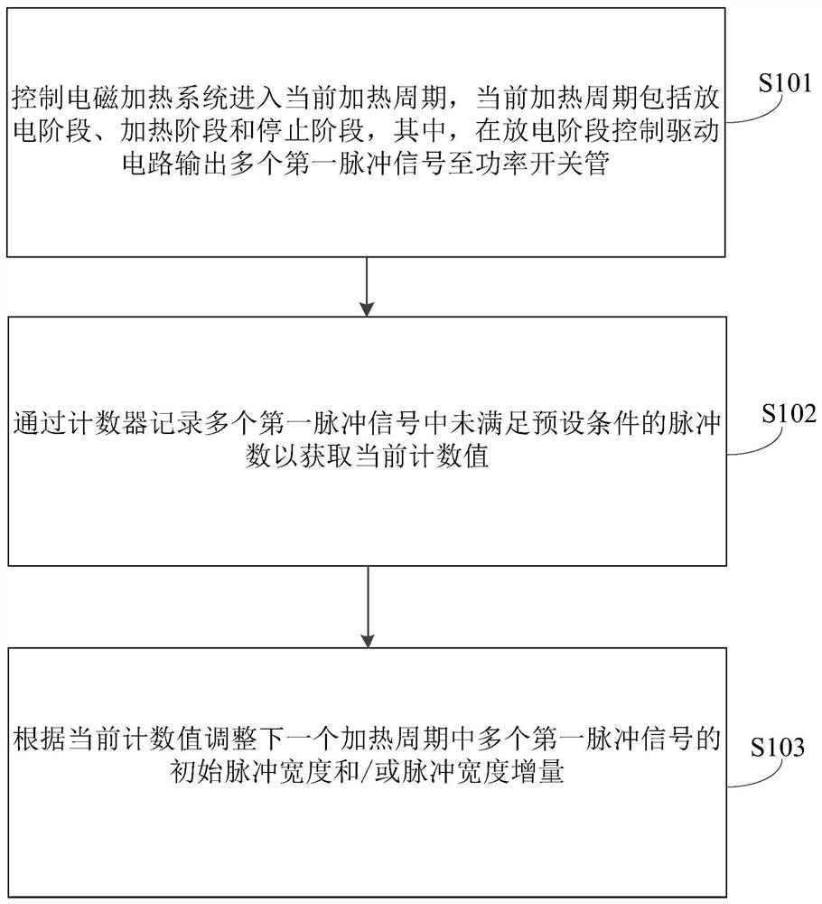
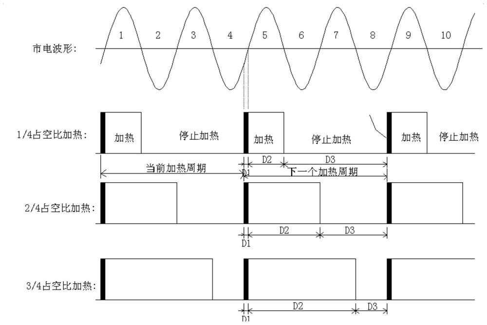
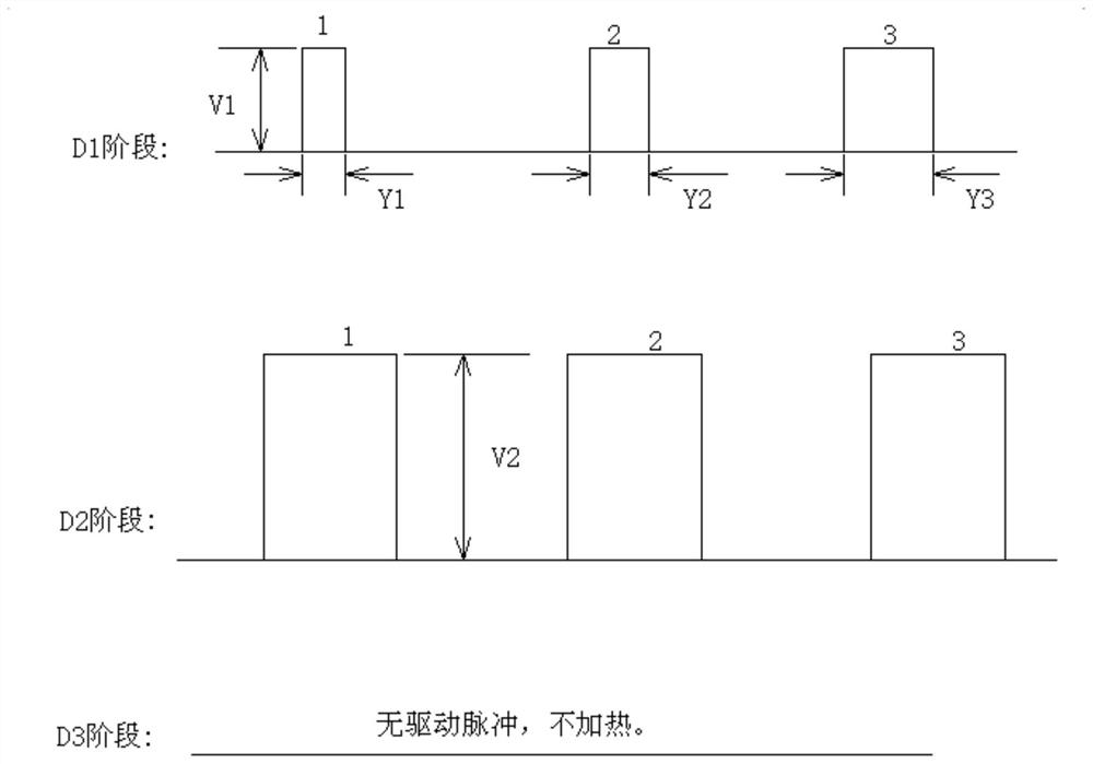
[0033] figure 1 is a flow chart of the control method of the electromagnetic heating system according to the embodiment of the present invention. Among them, the electromagnetic heating system includes a resonant heating circuit, a synchronous circuit, a power switch tube and a driving circuit.

[0034] Such as figure 1 As sh...


PUM


Abstract

The invention discloses an electromagnetic heating system and its control method. The electromagnetic heating system includes a resonant heating circuit, a synchronous circuit, a power switch tube and a driving circuit. The method includes the following steps: controlling the electromagnetic heating system to enter the current heating cycle, and the current heating cycle It includes a discharge phase, a heating phase and a stop phase, wherein in the discharge phase, the drive circuit is controlled to output multiple first pulse signals to the power switch tube; the number of pulses that do not meet the preset conditions in the multiple first pulse signals is recorded by a counter to obtain The current count value; adjust the initial pulse width and / or pulse width increment of a plurality of first pulse signals in the next heating cycle according to the current count value, so that the driving pulse width and / or pulse width increment of the driving circuit can be automatically adjusted, Effectively suppress pulse current. The invention also discloses an electromagnetic heating device.

Description

technical field [0001] The invention relates to the technical field of living appliances, in particular to a control method of an electromagnetic heating system, an electromagnetic heating system and an electromagnetic heating device. Background technique [0002] A related electromagnetic heating system such as an induction cooker usually drives the IGBT tube through a driving circuit, that is, the driving circuit can provide a driving signal to the IGBT tube to control the IGBT tube to be turned on or off. A low-power heating induction cooker adopts the wave-dropping method to realize low-power heating. In the low-power stage, it adopts a lower than normal driving voltage for discharge treatment, and requires a small pulse width. The heating phase is driven with normal voltage at normal width. However, different types of IGBT tubes or peripheral drive circuit parameters cause different responses to the PPG width. In the low-power discharge stage, due to the small pulse wi...

Claims


Application Information

Patent Timeline
Patent Type & Authority Patents(China)
IPC IPC(8): H05B6/06
CPCH05B6/06H05B6/062
Inventor 江德勇王云峰
Owner FOSHAN SHUNDE MIDEA ELECTRICAL HEATING APPLIANCES MFG CO LTD
Why Eureka
Try Eureka