Mold spraying frame

A technology of spraying racks and molds, applied in the direction of spraying devices, etc., can solve the problems of untimely opening and closing, complex equipment, uneven atomization, etc., and achieve the effects of preventing paint waste, ensuring sealing performance, and improving production efficiency

Pending Publication Date: 2019-04-09
CHONGQING BOAO MG AL MANUFACUTURE
View PDF11 Cites 1 Cited by
  • Summary
  • Abstract
  • Description
  • Claims
  • Application Information

AI Technical Summary

Problems solved by technology

[0005] (1) The flow adjustment is not uniform, resulting in inconsistent spraying thickness on the mold surface;
[0006] (2) The flow channel is easy to block and difficult to clean;
[0007] (3) The atomization is uneven and easy to form drops;
[00...

Method used


Image

  • Mold spraying frame
  • Mold spraying frame
  • Mold spraying frame

Examples


Embodiment

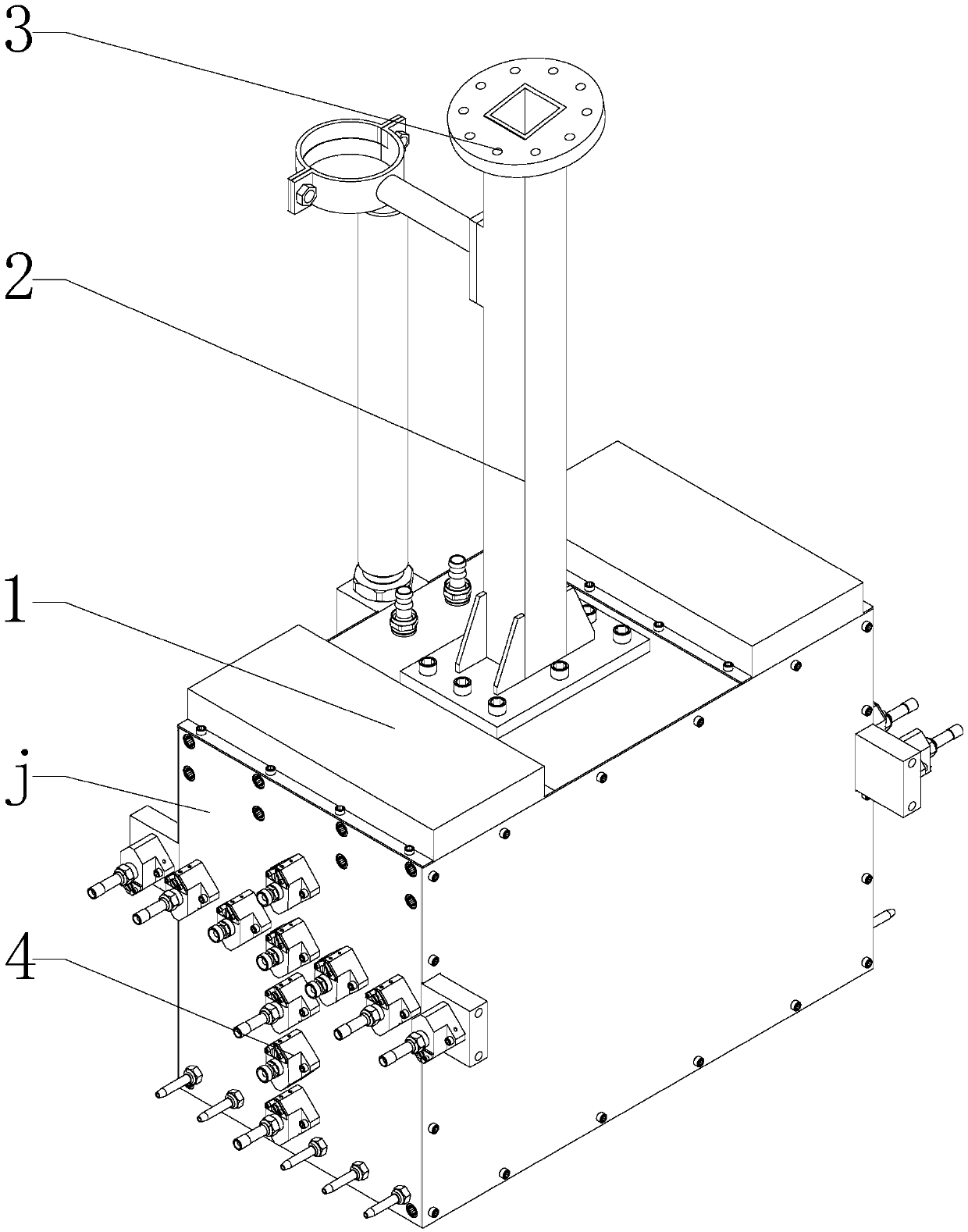
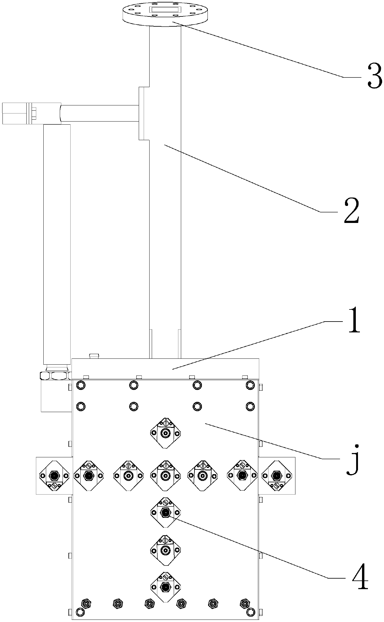
[0063] Such as Figure 1-12 As shown, a kind of mold spraying stand, its key is: comprise spraying base 1, spraying base 1 is connected with cantilever 2, cantilever 2 one end is connected with spraying base 1, and the other end end is provided with connecting plate 3, and connecting plate 3 is provided with There are screw holes, and the spraying seat 1 is provided with at least one spraying facade j, and the spraying facade j is provided with a horizontal nozzle group and a vertical nozzle group, and the horizontal nozzle group is composed of a plurality of horizontally arranged nozzles 4, and the vertical nozzle group It consists of multiple nozzles 4 arranged vertically.

[0064] The spraying seat 1 includes a cubic box, and two opposite vertical sides of the box form a spraying facade j, on which the horizontal nozzle group and the vertical nozzle group are arranged in a "cross" shape.

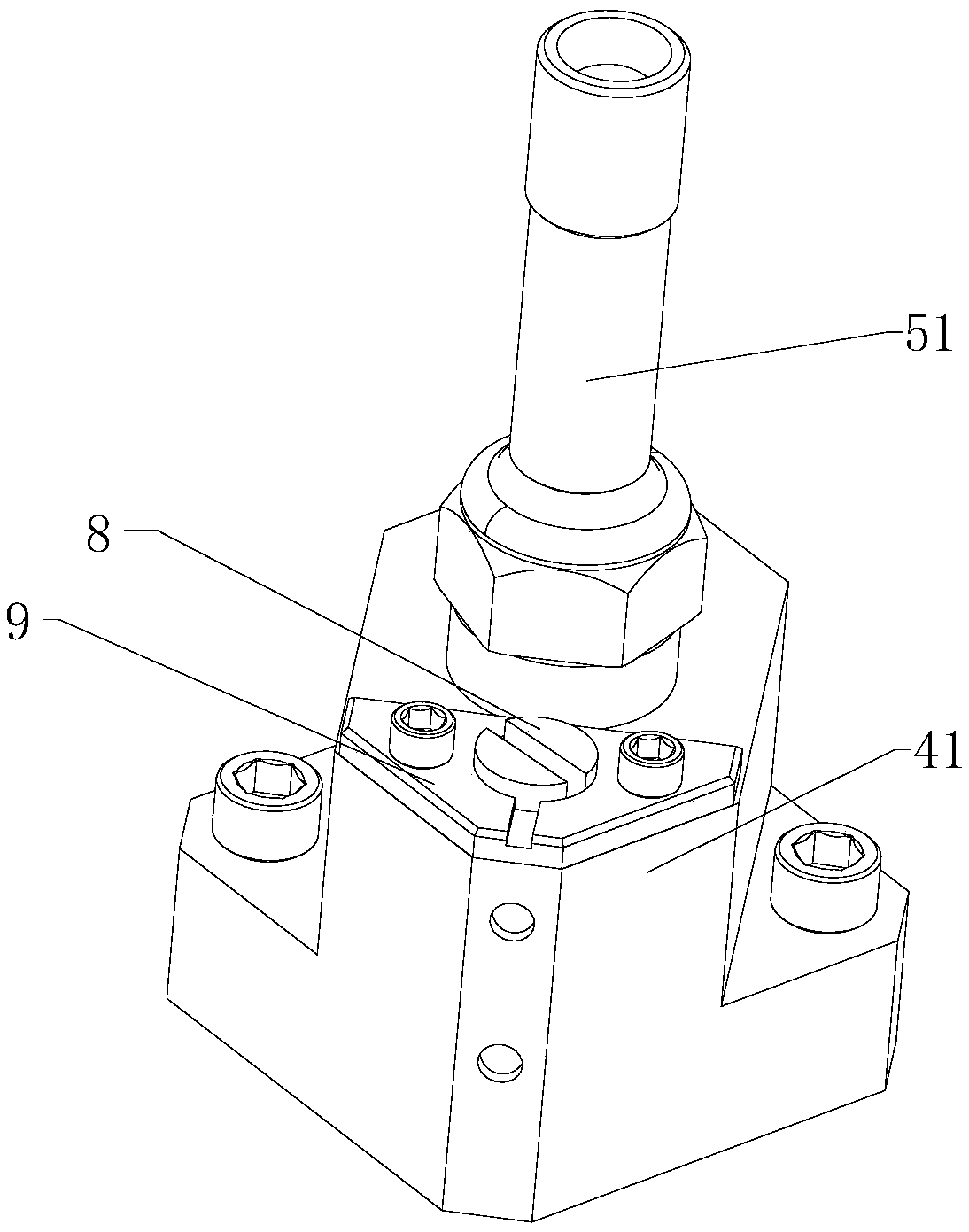
[0065] The nozzle 4 includes a nozzle seat 41, the nozzle seat 41 is provided with a...

Embodiment approach

[0083] One of the implementation methods is: the diameter ratio of the direct current hole o to the constriction hole q is 2:1, the diameter ratio of the atomization hole s to the constriction hole q is 4.3:1, the axial length of the constriction hole q and its diameter The ratio is 1.8:1, the axial length of the contraction extension tube 10 and the axial length of the contraction hole q are 1:1, and the ratio of the outer diameter of the contraction extension tube 10 to the diameter of the atomization hole s is 2:1.

[0084] Another embodiment is: the diameter ratio of the direct current hole o to the constriction hole q is 2.5:1, the diameter ratio of the atomization hole s to the constriction hole q is 4.8:1, the axial length of the constriction hole q and its diameter The ratio is 2.2:1, the axial length of the contraction extension tube 10 and the axial length of the contraction hole q are 1:1, and the ratio of the outer diameter of the contraction extension tube 10 to th...


PUM


Abstract

The invention discloses a mold spraying frame which comprises a spraying seat. The spraying seat is connected with a cantilever. One end of the cantilever is connected with the spraying seat, and a connecting disc is arranged at the other end of the cantilever and is provided with a screw hole. The spraying seat is provided with at least one spraying vertical face. A transverse nozzle set and a vertical nozzle set are arranged on each spraying vertical face. Each transverse nozzle set is formed by multiple transversely-distributed nozzles. Each vertical nozzle set is formed by multiple vertically-distributed nozzles. The mold spraying frame can carry out coating spraying on a mold stably and can be started and stopped fast, coating waste can be avoided, the environment can be protected, the spraying angle and direction can be adjusted, and the pressure casting spraying time can be effectively shortened; and the nozzles facilitate the work of coating flow adjusting and clearing, and thespraying efficiency can be effectively guaranteed.

Description

technical field [0001] The invention relates to spraying equipment, in particular to a mold spraying rack. Background technique [0002] The die-casting process uses high pressure to hydraulically inject metal into the mold cavity, and the molten metal is cooled and solidified under pressure to form a casting. The die-casting process can manufacture metal parts with complex shapes, clear outlines, thin walls and deep cavities, and the utilization rate of materials is high. Spraying is an important link in the die-casting process. It can effectively prevent the die-casting from welding with the die-casting mold, reduce the frictional resistance when the die-casting is ejected, prevent the mold from sticking, and play a cooling role; after spraying, the mold needs to be blown dry. [0003] Since the latent heat of crystallization of magnesium alloy is smaller than that of aluminum alloy, the solidification time is faster, and it is more sensitive to the mold temperature. If ...

Claims


Application Information

Patent Timeline
IPC IPC(8): B05B13/02B05B13/04B05B15/62B05B15/68B05B12/04
CPCB05B12/04B05B13/0278B05B13/0421B05B15/62B05B15/68Y02P70/10
Inventor 傅建设陈佳朱卓然
Owner CHONGQING BOAO MG AL MANUFACUTURE
Why Eureka
Try Eureka