Ultrasonic C-scan automatic detecting system

An automatic detection, ultrasonic technology, applied in the direction of material analysis, measurement device, instrument, etc. using sonic/ultrasonic/infrasonic waves, can solve the left and right drift of surface echo, large workpiece clamping error, axial runout and The radial runout cannot meet the requirements, etc., to achieve the effect of high precision, suppression of agitation, and avoidance of influence

Active Publication Date: 2019-05-10
CHINA WEAPON SCI ACADEMY NINGBO BRANCH
View PDF16 Cites 0 Cited by
  • Summary
  • Abstract
  • Description
  • Claims
  • Application Information

AI Technical Summary

Problems solved by technology

[0004] The existing design of the water tank and turntable will cause slight deformation of the bottom due to long-term water storage in the water tank, which will affect the mechanical precision of the turntable; in addition, the detection system has high requirements for the mechanical precision of the turntable. If the radial runout does not meet the requirements, it will lead to large clamping errors of the workpiece, serious left and right drift of the surface echo during the high-speed rotation of the workpiece, and it is difficult to realize the tracking of the curved surface of the workpiece by the industrial robot and the automatic alignment of the ultrasonic sound beam ; In view of this, it is necessary to provide a new ultrasonic C-scan automatic detection system

Method used


Image

  • Ultrasonic C-scan automatic detecting system
  • Ultrasonic C-scan automatic detecting system
  • Ultrasonic C-scan automatic detecting system

Examples


Embodiment Construction

[0022] The present invention will be further described in detail below in conjunction with the accompanying drawings and embodiments.

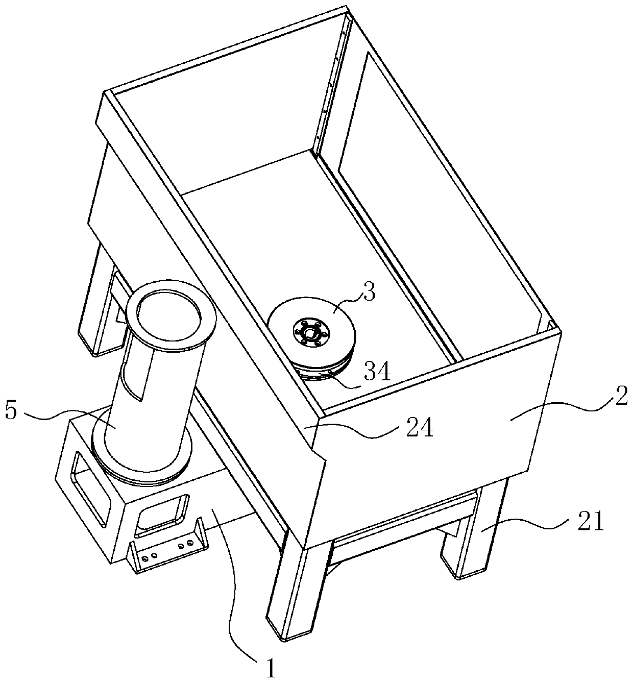
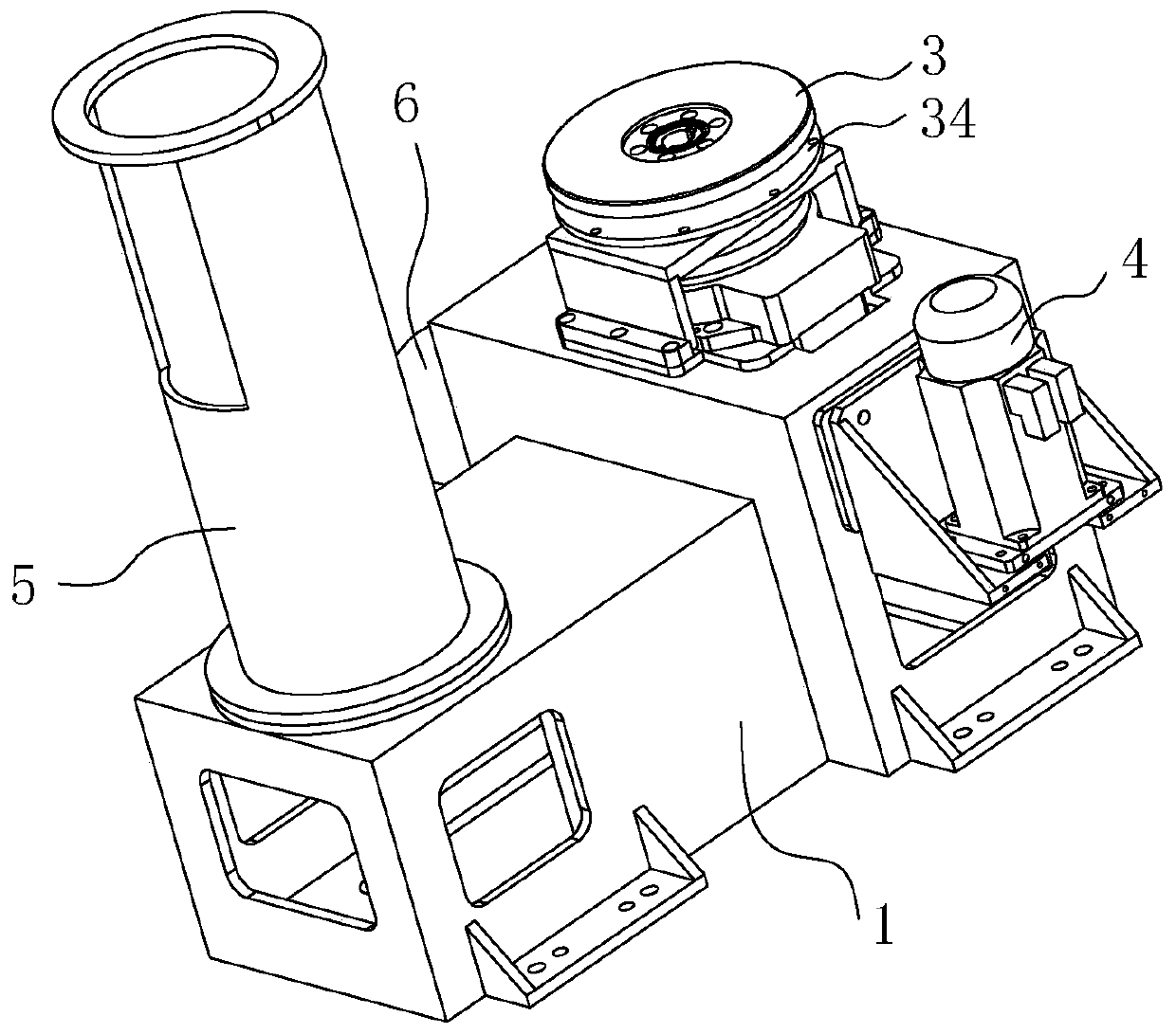
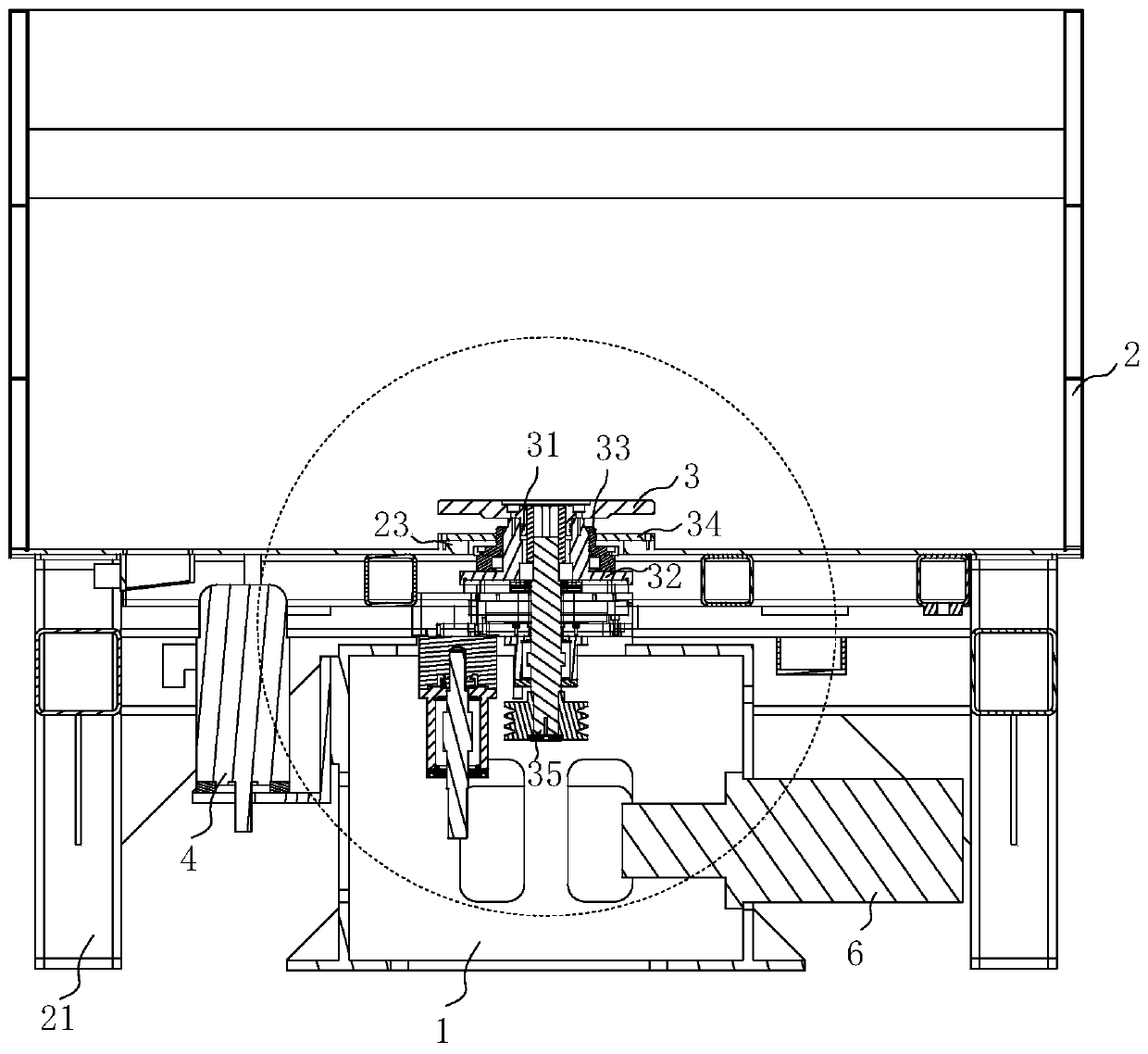
[0023] refer to Figure 1 to Figure 5 As shown, this preferred embodiment provides an automatic ultrasonic C-scan detection system, including a first base 1, an industrial robot (only partially shown) located on the first base 1, a water tank 2, for supporting The second base 21 of the water tank 2 and the turntable 3 arranged inside the bottom of the water tank 2 .

[0024] In this technical solution, the turntable 3 is fixed by the first base 1, and the water tank is fixed by the second base 21. The first base 1 and the second base 21 are set independently of each other, and the second base 21 is erected on the second base. On a base 1, and the first base 1 is independently supported on the bottom surface by foot bolts, and the second base 21 is also independently supported on the bottom surface.

[0025] In this preferred embodiment, the ...


PUM


Abstract

The invention discloses an ultrasonic C-scan automatic detecting system. The ultrasonic C-scan automatic detecting system includes a first base, an industrial robot, a water tank, a second base for supporting the water tank, a turntable disposed on the inner side of the bottom of the water tank and a first driving mechanism for driving the turntable to rotate. The second base is mounted on the first base, a through hole is formed in the bottom of the water tank, a flange is arranged on the periphery of the through hole, and the turntable penetrates through the through hole and arranged on theinner side of the bottom of the water tank in a protruding mode; the turntable is provided with a lower sleeving connecting part, a main shaft is arranged on the outer wall of the lower sleeving connecting part in a sleeving mode, and the main shaft extends downward to the outer part of the water tank and is driven to rotate by the first driving mechanism. A mounting part is arranged outside the main shaft in a sleeving mode, and the upper end of the mounting part extends upward and is higher than the flange, the lower end of the mounting part extends downwardly to form an annular closed spacewith the through hole, and the upper end of the main shaft extends upward and is higher than the upper end of the mounting part. The ultrasonic C-scan automatic detecting system has the advantages that the first base and the second base are independently arranged, and the mechanical precision of the turntable is not affected even if the water tank is slightly deformed at the bottom due to long-term water storage.

Description

technical field [0001] The invention relates to the technical field of ultrasonic scanning devices, in particular to an ultrasonic C-scan automatic detection system. Background technique [0002] The digital, graphic and intelligent detection methods of ultrasonic C-scan automatic detection technology can reduce the influence of human factors, can intuitively reproduce the size and shape of internal defects of the workpiece, realize the qualitative, positioning and quantitative detection of defects, and improve the reliability and reliability of detection results. stability. In particular, the use of ultrasonic C-scan automatic detection technology is involved in the use of ultrasonic C-scan automatic detection technology for missile warhead components, engine casings and other rotary body workpieces with complex surfaces. [0003] Due to the high positioning accuracy of the multi-degree-of-freedom articulated industrial robot, it can move to any position and posture in a f...

Claims


Application Information

Patent Timeline
Patent Type & Authority Applications(China)
IPC IPC(8): G01N29/265G01N29/28
Inventor 倪培君张荣繁乔日东郭智敏李雄兵张维国唐盛明徐向群李红伟左欣齐子诚王晓艳
Owner CHINA WEAPON SCI ACADEMY NINGBO BRANCH
Why Eureka
Try Eureka