Two-phase dynamic synchronous clock generating circuit applied to charge pump system

A technology for synchronizing clocks and generating circuits. It is applied in the direction of conversion equipment without intermediate conversion to AC. It can solve problems such as inapplicability, failure to output high voltage circuits, and poor phase synchronization effects, and achieve good application value.

A technology for synchronizing clocks and generating circuits. It is applied in the direction of conversion equipment without intermediate conversion to AC. It can solve problems such as inapplicability, failure to output high voltage circuits, and poor phase synchronization effects, and achieve good application value.

CN109756104APending Publication Date: 2019-05-14CRM ICBG (WUXI) CO LTD

Image

  • Two-phase dynamic synchronous clock generating circuit applied to charge pump system
  • Two-phase dynamic synchronous clock generating circuit applied to charge pump system
  • Two-phase dynamic synchronous clock generating circuit applied to charge pump system

Examples


Embodiment Construction

[0037] In order to describe the technical content of the present invention more clearly, further description will be given below in conjunction with specific embodiments.

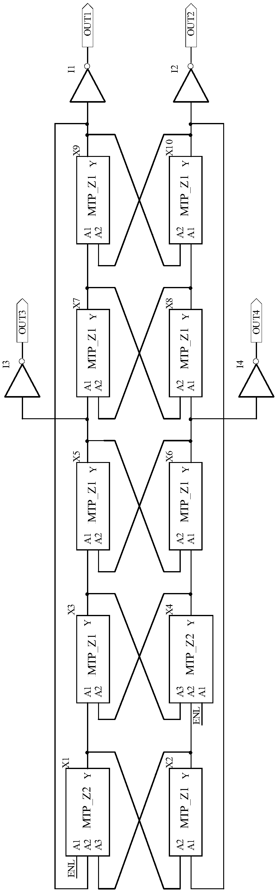
[0038] see image 3 As shown, it is a schematic diagram of the circuit structure of the two-phase dynamic synchronous clock generation circuit applied to the charge pump system of the present invention. The two-phase dynamic synchronous clock generation circuit applied to the charge pump system, its main feature is that the two-phase dynamic synchronous clock generation circuit includes:

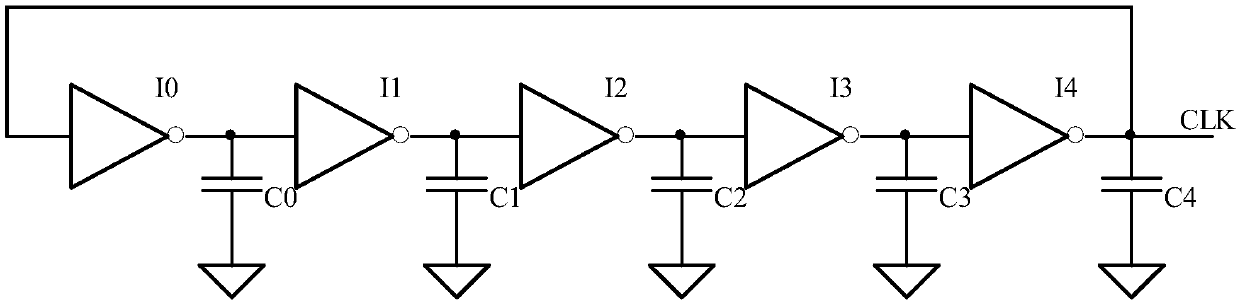
[0039] The first ring oscillator is composed of odd-numbered oscillator modules connected end to end, and is used to generate synchronous clock signals;

[0040] The second ring oscillator is composed of odd-numbered oscillation modules connected end to end, and interacts with the first ring oscillator to generate a synchronous clock signal;

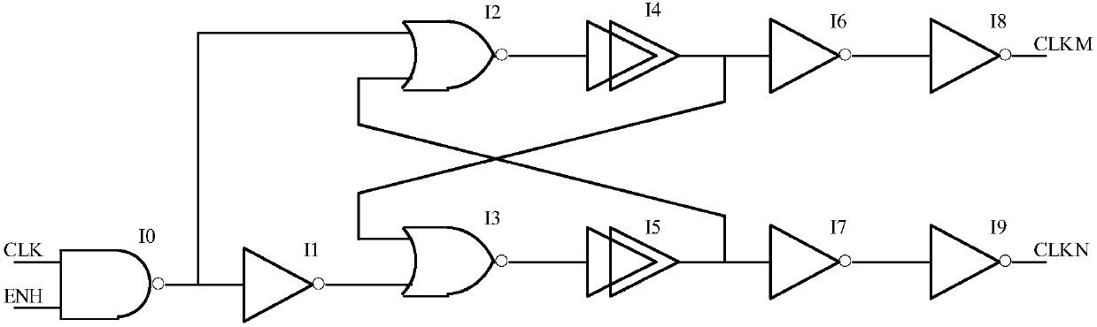
[0041] At least two inverters, the input terminals of the at least two invert...


PUM


Abstract

The invention relates to a two-phase dynamic synchronous clock generating circuit applied to a charge pump system. The two-phase dynamic synchronous clock generating circuit comprises a first path ofring oscillator and a second path of ring oscillator. By adoption of the two-phase dynamic synchronous clock generating circuit applied to the charge pump system, when the output clock signals sufferfrom asynchronous phase change, a dynamic synchronization effect is achieved through mutual promotion and acceleration via the two paths of synergistic ring oscillators, so that the circuit can be applied to occasions with relatively high requirements on frequency and phase synchronization, and has a higher application value.

Description

technical field [0001] The invention relates to the technical field of digital chips, in particular to the technical field of clock synchronization, in particular to a two-phase dynamic synchronous clock generation circuit applied to a charge pump system. Background technique [0002] In the digital chip system, the clock signal occupies a very important position. Such as digital-to-analog converter ADC, data interface circuit, charge pump circuit, etc., all need an accurate clock signal. The clock signal is generally generated by an external clock source or crystal oscillator, but when the external clock source cannot provide the required frequency and phase, it is necessary to design a clock generation circuit inside the chip to generate the clock signal. In a standard CMOS process, a ring oscillator is usually used to generate the oscillation frequency. [0003] see figure 1 As shown, it is a schematic diagram of the circuit structure of a ring oscillator in the prior ...

Claims


Application Information

Patent Timeline
14 May 2019
Publication
CN109756104A
IPC
H02M3/07
CPC
Y02B70/10
Inventors
冯雪阳; 曹旺