Light distribution module

A light distribution and optical technology, applied in lighting and heating equipment, parts of lighting devices, lighting devices, etc., can solve problems such as high cost and multiple maintenance costs, and achieve the effect of reducing the number of designs

Active Publication Date: 2019-05-21
LITE ON ELECTRONICS (GUANGZHOU) LTD +1
View PDF7 Cites 0 Cited by
  • Summary
  • Abstract
  • Description
  • Claims
  • Application Information

AI Technical Summary

Problems solved by technology

[0003] However, lighting fixtures for road lighting are often time-consuming and costly to develop
Furthermore, each additional lighting device also means an additional maintenance cost

Method used


Image

  • Light distribution module
  • Light distribution module
  • Light distribution module

Examples


Embodiment Construction

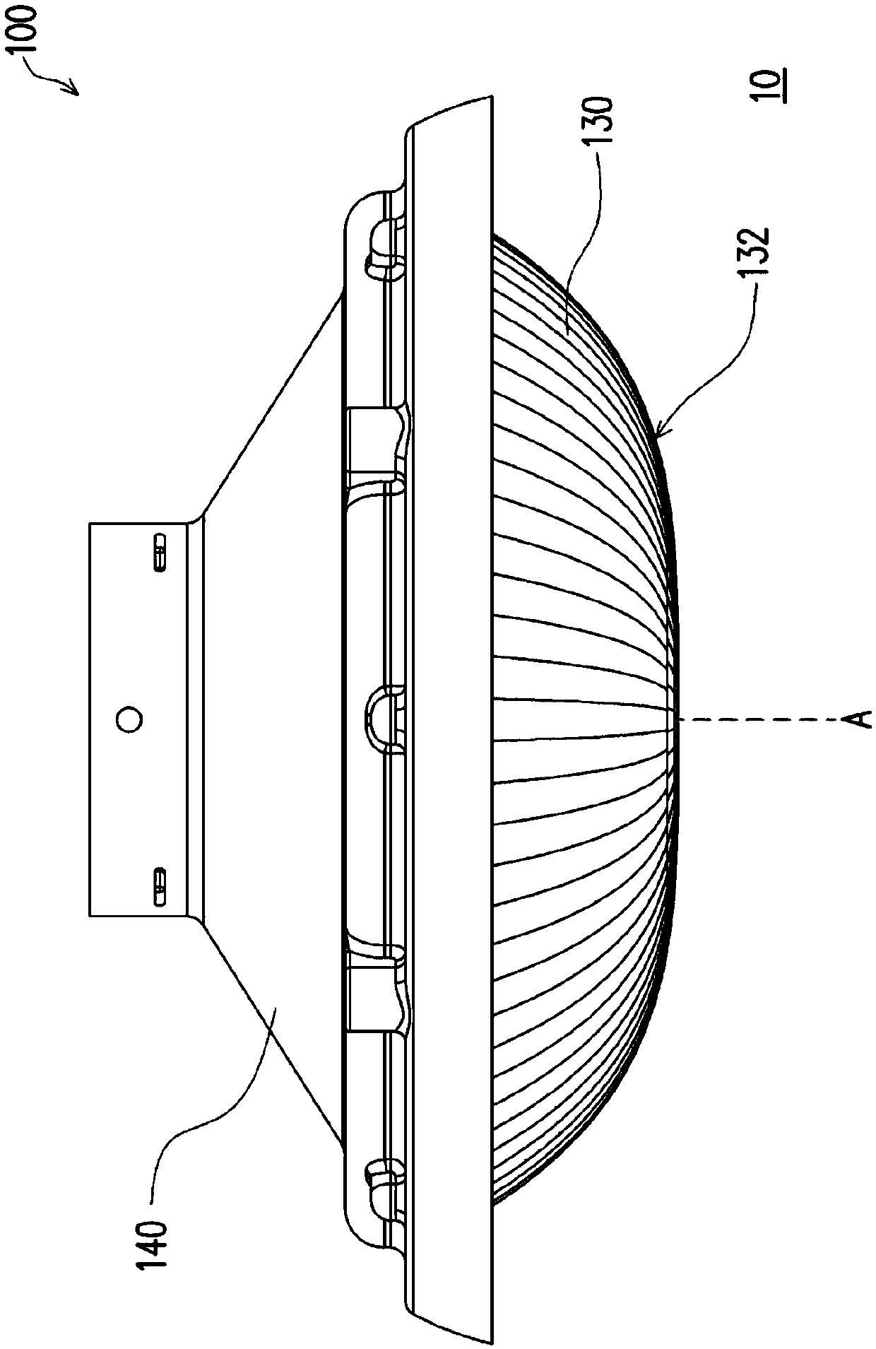
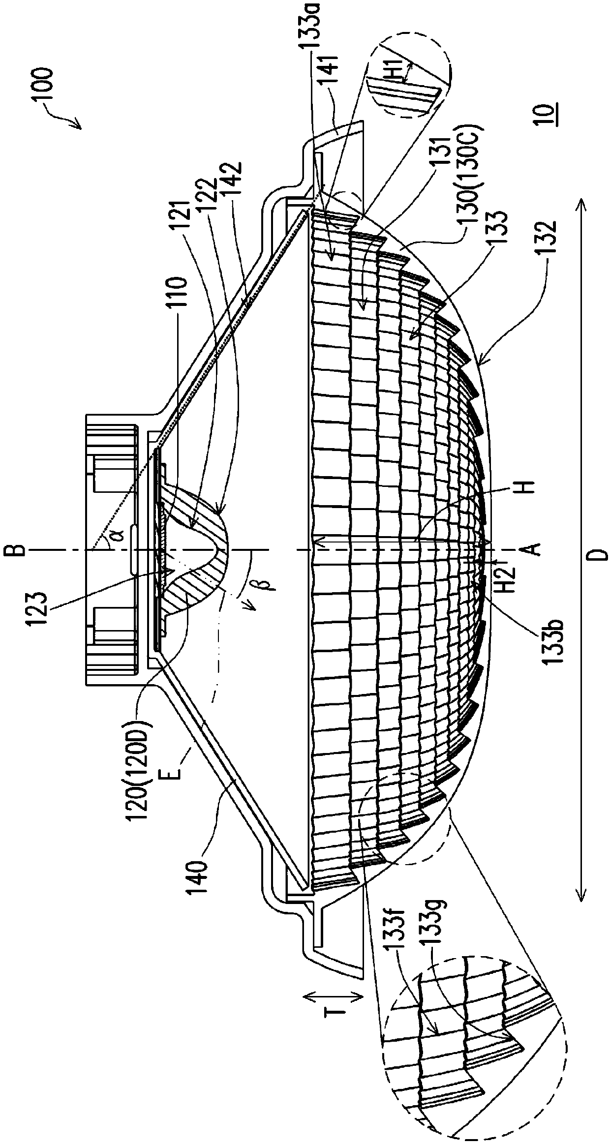
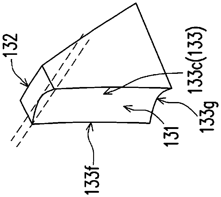
[0045] Figure 1A It is a schematic side view of the lighting device according to the first embodiment of the present invention. Figure 1B for Figure 1A A schematic cross-sectional view of the illumination device cut along the optical axis A. Figure 2A to Figure 2C It is a schematic diagram of three sub-surfaces of the optical housing in the embodiment of the present invention. Figure 3A to Figure 3B It is a three-dimensional schematic view of the lens of the embodiment of the present invention. Figure 3C and Figure 3D respectively Figure 3B The schematic cross-sectional view of the lens along the second major axis B2 and the first major axis B1. Figure 4A to Figure 4B It is a three-dimensional schematic diagram of a lens according to another embodiment of the present invention. Figure 4C and Figure 4D respectively Figure 4B The schematic cross-sectional view of the lens along the longitudinal direction B3 and the transverse direction B4. Figure 5A to...


PUM


Abstract

A light distribution module configured to control light distribution of a light source includes a lens and an optical cover. The lens has a first light-incident surface, a first light-emitting surfaceopposite to the first light-incident surface, and an accommodating recess located at a side of the first light-incident surface, wherein the accommodating recess is configured to contain the light source. The optical cover covers the lens and has a second light-incident surface and a second light-emitting surface opposite to the second light-incident surface, wherein the second light-incident surface is located between the first light-emitting surface and the second light-emitting surface, and the second light-incident surface has a plurality of sub-curved surfaces. Boundaries between adjacent sub-curved surfaces are bent-shaped with respect to the adjacent sub-curved surfaces.

Description

technical field [0001] The invention relates to an optical module, and in particular to a light distribution module. Background technique [0002] In the design of traditional lighting devices, the light source is arranged on the optical housing to generate the required light shape. For lighting devices used for road lighting, in order to comply with lighting device installation regulations in different countries and different lighting requirements in different regions, the same lighting device often needs to design several or even dozens of optical housings to meet the requirements. Regulations and regional lighting needs. [0003] However, lighting fixtures for road lighting are often time-consuming and costly to develop. Furthermore, each additional lighting device also means an additional maintenance cost. Therefore, for manufacturers of lighting devices for road lighting, there is an urgent need for a lighting device that can reduce the number of developments of ligh...

Claims


Application Information

Patent Timeline
Patent Type & Authority Applications(China)
IPC IPC(8): F21V5/04F21V5/08
Inventor 施威文王世昌
Owner LITE ON ELECTRONICS (GUANGZHOU) LTD
Why Eureka
Try Eureka