Flushing system and flushing method for blast furnace soft water pipeline

A flushing system and soft water technology, applied in the direction of cooling devices, etc., can solve the problem that cooling wall branch pipes cannot be flushed at the same time, and achieve the effects of good flushing quality, improved flushing efficiency, and fast flushing speed

Active Publication Date: 2019-05-28
ANHUI MA STEEL EQUIP MAINTENANCE CO LTD
View PDF5 Cites 2 Cited by
  • Summary
  • Abstract
  • Description
  • Claims
  • Application Information

AI Technical Summary

Problems solved by technology

For example, Chinese patent: application number: 201711337221.8, publication date: May 18, 2018, the invention discloses a backwashing method for the stave of a blast furnace, which can ensure the flushing effect of the stave without affecting the soft water main pipe that has been flushed , branch pipes, but the patent does not involve the flushing method of the main pipe and branch pipes, and the flushing water enters the cooling wall from the furnace bottom water-cooled pipe into the furnace top water supply ring pipe, and due to the small flow rate, the flushing of each cooling wall branch pipe cannot be performed at the same time It needs to be implemented in batches according to the flow of water supply

Method used


Image

  • Flushing system and flushing method for blast furnace soft water pipeline
  • Flushing system and flushing method for blast furnace soft water pipeline

Examples


Embodiment 1

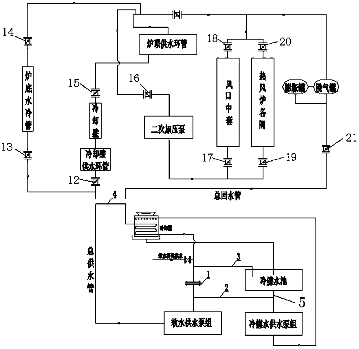
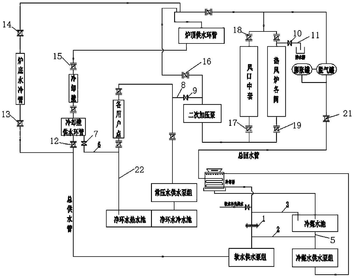
[0030] Such as figure 1 , figure 2 As shown, a blast furnace soft water pipeline flushing system includes soft water supply pumps, hot blast furnace valves, secondary pressure pumps, cooling walls, refrigerant pools, main water supply pipes, main return water pipes and several valves.

[0031] Such as figure 1 As shown, the soft water main water supply pipe and the main return water pipe are respectively disconnected, and a connecting pipe 4 is added at the bottom of the blast furnace to connect the main water supply pipe and the main return water pipe; a blind plate 1 is added between the soft water main return water pipe and the soft water supply pump group A water supply pipe 2 is added at the end of the soft water supply pump group, and the water supply pipe 2 is connected to the outlet pipe 5 of the refrigerant pool and then communicated with the refrigerant pool, so that the soft water main water supply pipe and the main return water pipe are connected at the bottom of...

Embodiment 2

[0051] Using the flushing system and flushing method of blast furnace soft water pipeline in implementation 1, this method is used in Changjiang Iron and Steel 1080m 3 Blast furnace, Masteel No. 2 Iron and Steel General Plant 2500m 3 Blast furnace, 3200m 3 Used in blast furnace construction, the flushing was completed within a week, and the flushing quality met the specification requirements through pipe cutting inspection.


PUM


Abstract

The invention discloses a flushing system for a blast furnace soft water pipeline. A communication pipe is additionally arranged between a soft water main water supply pipe and a main return pipe. A blind plate is additionally arranged between the soft water main return pipe and a soft water supply pump group. A water supply pipe is additionally arranged at the end of the soft water supply pump group. The water supply pipe is connected with a water outlet pipe of a refrigerant water pool and further communicated with the refrigerant water pool, so that the soft water main water supply pipe andthe main return pipe are communicated at the bottom position of a blast furnace. A drain pipe I is additionally arranged between the portion, behind a cooler, of the main return pipe and the refrigerant water pool. The invention further discloses a flushing method for the blast furnace soft water pipeline. The startup of a soft water pump is ensured by the method of introducing water from the refrigerant water pool. By introducing normal-pressure water in front of a secondary pressurization pump, the startup of the secondary pressurization pump is ensured, and the flushing of the whole main pipe and branch pipes is completed; and backwashing of the cooling wall is directly carried out through normal-pressure water, so that the flushing speed is high, the flushing efficiency is improved, and the flushing quality is good through pipe cutting inspection after flushing.

Description

technical field [0001] The invention relates to the field of iron and steel metallurgy, in particular to a method for flushing blast furnace soft water pipelines. Background technique [0002] The blast furnace soft water system is a closed circulation system. The soft water is used for the cooling of the blast furnace bottom water cooling pipe, cooling wall, straight blow pipe, tuyere jacket, hot blast valve and shutoff valve. When the soft water is supplied to the bottom of the blast furnace by the soft water supply pump group, it is divided into two paths, one path is supplied to the furnace top through the furnace bottom water cooling pipe and the direct blow pipe, the other path is supplied to the furnace top through the cooling wall, and the two paths of water flow to the furnace top at the furnace top After the soft water ring pipe, it flows into the secondary pressurization pump group. After pressurization, it is divided into two channels, one is used for cooling the...

Claims


Application Information

Patent Timeline
Patent Type & Authority Applications(China)
IPC IPC(8): C21B7/10
Inventor 章锐晋杰邓传启崔学峰朱绍林
Owner ANHUI MA STEEL EQUIP MAINTENANCE CO LTD
Why Eureka
Try Eureka