Waste heat utilization device for vehicles

A waste heat, vehicle technology, applied in vehicle components, transportation and packaging, heating/cooling equipment, etc., to achieve stable heating

Active Publication Date: 2022-06-07
HONDA MOTOR CO LTD
View PDF7 Cites 0 Cited by
  • Summary
  • Abstract
  • Description
  • Claims
  • Application Information

AI Technical Summary

Problems solved by technology

On the other hand, an electric vehicle without an engine uses waste heat from the drive motor or an electric heater to heat the heating medium, and the interior of the vehicle is heated by dissipating the heat of the heating medium through the heater core.

Method used


Image

  • Waste heat utilization device for vehicles
  • Waste heat utilization device for vehicles
  • Waste heat utilization device for vehicles

Examples


no. 2 Embodiment approach

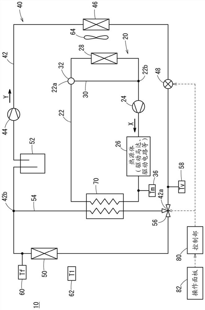
[0105] [2.1. Structure of the vehicle waste heat utilization device 10 ]

[0106] Figure 8 The configuration of the vehicle waste heat utilization device 10 according to the second embodiment shown is similar to that in various aspects. figure 1 The vehicle waste heat utilization device 10 according to the illustrated first embodiment is the same. The same structure is denoted by the same symbol, and the description thereof is omitted.

[0107] In the air-conditioning side flow path 42, in addition to the air-conditioning side first connection portion 42a and the air-conditioning side second connection portion 42b, an air-conditioning side third connection portion 42a and the air-conditioning side radiator 50 are provided between the air-conditioning side first connection portion 42a and the air-conditioning side radiator 50. connecting portion 42c. In addition, the air-conditioning side bypass flow path 54 is connected to the air-conditioning side first connection portion...


PUM


Abstract

The invention relates to a vehicle waste heat utilization device. An air-conditioning side bypass flow path (54) and a first switching valve (56) are arranged on the air-conditioning side flow path (42), wherein the air-conditioning side bypass flow path (54) is connected to the air-conditioning side radiator ( 50) on the upstream side of the air-conditioning side first connecting portion (42a) and on the downstream side of the air-conditioning side second connecting portion (42b); the first switching valve (56) switches the air-conditioning side of the first connecting portion (42a ), the communication and blockage of the air-conditioning side flow path (42) on the upstream side, the air-conditioning side flow path (42) on the downstream side and the air-conditioning side bypass flow path (54). The vehicle waste heat utilization device (10) further includes a heat exchanger (70) straddling the cooling side flow path (22) on the downstream side of the heat source body (26) and the first switching valve (56). The air-conditioning side on the downstream side bypasses the flow passage (54), and heat exchange is performed between the first heat medium and the second heat medium. Accordingly, stable heating can be performed without reducing the heating capacity.

Description

technical field [0001] The present invention relates to a waste heat recovery device for a vehicle that uses waste heat of a heat source body such as a drive motor provided in an electric vehicle to heat the interior of a vehicle. Background technique [0002] A vehicle equipped with an engine cools the engine by absorbing the residual heat of the engine with a heating medium, and heats the interior of the vehicle by dissipating the heat of the heating medium with a heater core. On the other hand, an electric vehicle without an engine uses the residual heat of the drive motor or the electric heater to heat the heat medium, and the interior of the vehicle is heated by dissipating the heat of the heat medium by the heater core. [0003] Japanese Patent Application Laid-Open No. 2012-76589 discloses an air conditioner that uses a heat pump circuit to heat the interior of a vehicle, in which a heat medium is heated by a compressor and then heated by an indoor heat exchanger ( H...

Claims


Application Information

Patent Timeline
Patent Type & Authority Patents(China)
IPC IPC(8): B60H1/00B60H1/14
CPCY02A30/274
Inventor 野老洋介
Owner HONDA MOTOR CO LTD
Why Eureka
Try Eureka