Vehicular waste heat using device

A waste heat and vehicle technology, applied in vehicle components, transportation and packaging, heating/cooling equipment, etc.

Active Publication Date: 2019-06-28
HONDA MOTOR CO LTD
View PDF7 Cites 1 Cited by
  • Summary
  • Abstract
  • Description
  • Claims
  • Application Information

AI Technical Summary

Problems solved by technology

On the other hand, an electric vehicle without an engine uses waste heat from the drive motor or an electric heater to heat the

Method used


Image

  • Vehicular waste heat using device
  • Vehicular waste heat using device
  • Vehicular waste heat using device

Examples


no. 2 Embodiment approach

[0105] [2.1. Structure of Waste Heat Utilization Device 10 for Vehicles]

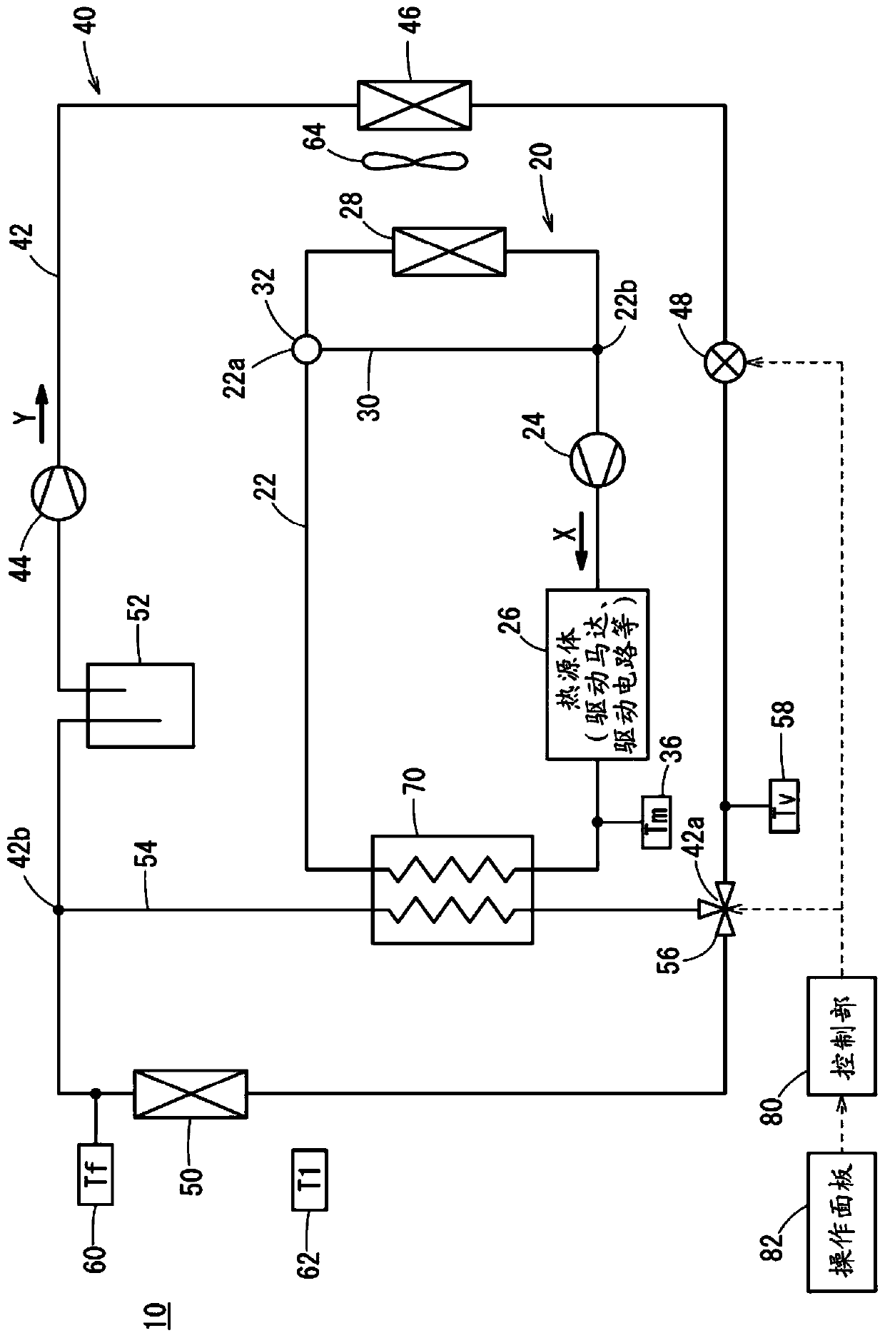
[0106] Figure 8 The structure of the vehicle waste heat utilization device 10 according to the second embodiment shown is different from that of figure 1 The vehicle waste heat utilization device 10 according to the first embodiment shown is the same. The same symbols are attached to the same structure, and descriptions thereof are omitted.

[0107] On the air-conditioning side flow path 42, in addition to the first air-conditioning side connecting portion 42a and the second air-conditioning side connecting portion 42b, there is also a third air-conditioning side connection between the first air-conditioning side connecting portion 42a and the air-conditioning side radiator 50. Connecting portion 42c. Furthermore, the air-conditioning side bypass flow path 54 is connected to the air-conditioning side first connection part 42a, the air-conditioning side second connection part 42b, and the air-conditi...


PUM


Abstract

The invention relates to a vehicular waste heat using device. An air conditioner side flow path (42) is provided with an air conditioner side bypass flow path (54) and a first switch (56), wherein theair conditioner side flow path (54) is connected between an air conditioner side first connecting part (42a) at the upstream side of an air conditioner side heat radiator (50) and a second connectingpart (42b) arranged at the downstream side. The first switch (56) performs switching for communicating or blocking the air conditioner side flow path (42) at the upstream side of the air conditionerside first connecting part (42a), the air conditioner side flow path (42) and an air conditioner side bypass flow path (54) at the downstream side. The vehicular waste heat using device (10) is also provided with a heat exchanger (70). The heat exchanger (70) bestrides a cooling side flow path (22) at the downstream side of a heat source (26), and the air conditioner side bypass flow path (54) atthe downstream side of the first switch (56). Heat exchanging is performed between a first heat medium and a second heat medium. Therefore, stable heat supplying can be realized without heat supplyingcapability reduction.

Description

technical field [0001] The present invention relates to a waste heat recovery device for a vehicle that heats a vehicle interior by using waste heat from a heat source such as a drive motor installed in an electric vehicle. Background technique [0002] A vehicle equipped with an engine cools the engine by absorbing waste heat of the engine with a heating medium, and heats a vehicle interior by dissipating the heat of the heating medium with a heater core. On the other hand, an electric vehicle without an engine heats the heating medium with waste heat from the drive motor or an electric heater, and the interior of the vehicle is heated by dissipating the heat of the heating medium through the heater core. [0003] Japanese Invention Patent Laid-Open Publication No. 2012-76589 shows an air conditioner that uses a heat pump circuit to heat the interior of a vehicle. heater core) to dissipate heat from the heat medium, and then use the outdoor heat exchanger (radiator) to abs...

Claims


Application Information

Patent Timeline
IPC IPC(8): B60H1/00B60H1/14
CPCY02A30/274
Inventor 野老洋介
Owner HONDA MOTOR CO LTD
Why Eureka
Try Eureka