a mechanical filter

A technology of mechanical filter and filter layer, which is applied in the direction of fixed filter elements, filter separation, chemical instruments and methods, etc. It can solve the problems of single filtering and washing methods, incomplete cleaning, and inability to clean mechanical filters at the same time.

Active Publication Date: 2020-11-13
黑龙江三幸环保科技有限公司
View PDF5 Cites 2 Cited by
  • Summary
  • Abstract
  • Description
  • Claims
  • Application Information

AI Technical Summary

Problems solved by technology

[0006] The present invention overcomes the deficiencies of the above-mentioned prior art and provides a mechanical filter to solve the problem that the existing mechanical filter cannot be cleaned at the same time, and the problem of incomplete cleaning caused by a single filtering and flushing method

Method used


Image

  • a mechanical filter
  • a mechanical filter
  • a mechanical filter

Examples


specific Embodiment approach 1

[0053] This embodiment is a mechanical filter embodiment.

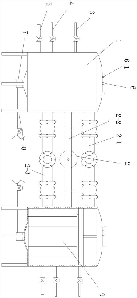
[0054] Such as Figure 1-5 As shown, a mechanical filter disclosed in this embodiment includes a tank body 1, water inlet and outlet components 2, upper air intake pipe 3, lower air intake pipe 4, reverse water inlet pipe 5, adjusting dial 6, lifting motor 7, and sewage pipe 8 and filter member 9; the tank body 1 is arranged symmetrically through the support rods, and the tank body 1 is connected by the water inlet and outlet components 2, and the upper air intake pipe 3, the lower air intake pipe 4 and the reverse air intake pipe 4 are arranged on the outer wall of the tank body 1 The water inlet pipe 5, the upper end of the tank body 1 is provided with an adjusting dial 6, the lower end of the tank body 1 is provided with a lifting motor 7 and a sewage pipe 8, and the inside of the tank body 1 is provided with a filter member 9;

[0055]Close the valves on the upper floor air intake pipe 3, the lower floor air inta...

specific Embodiment approach 2

[0064] This embodiment is an embodiment of an arc-adjusting filter layer.

[0065] It should be noted that the arc-shaped filter layer in this embodiment can be implemented independently, that is, it can exist independently as a part of a mechanical filter, and it can also be further limited to the mechanical filter described in the first embodiment.

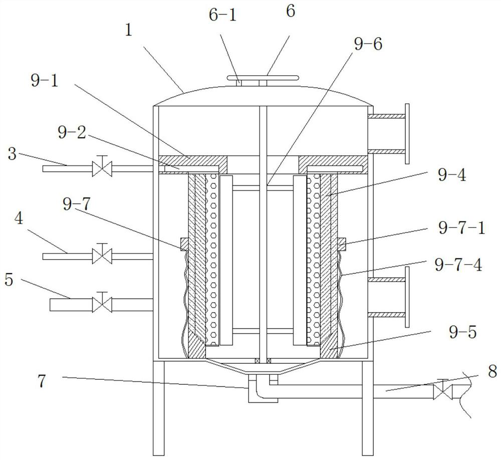
[0066] combine Figure 5 As shown, the arc-shaped filter layer facing the filter member disclosed in this embodiment includes an arc-shaped net cover 9-4-1, an arc-shaped net 9-4-2 and a filter medium 9-4-3, and the arc-shaped net cover 9 The upper wall of -4-1 is set in the annular groove 9-2 of the annular plate 9-1, and the upper wall of the arc net cover 9-4-1 has a through hole, and the arc net cover 9-4-1 The lower wall is arranged on the bottom of the inner wall of the tank body 1 through the arc retaining strip 9-5, the side wall of the arc net cover 9-4-1 is arranged on the side wall of the vertical beam 9-3, and the a...

specific Embodiment approach 3

[0069] This embodiment is an embodiment of an internal blocking member for a mechanical filter. It should be noted that the internal blocking member for a mechanical filter of this embodiment can be implemented separately, that is, it can exist alone as a part of a mechanical filter, and it can also be used for a mechanical filter described in the first embodiment. The device is further limited.

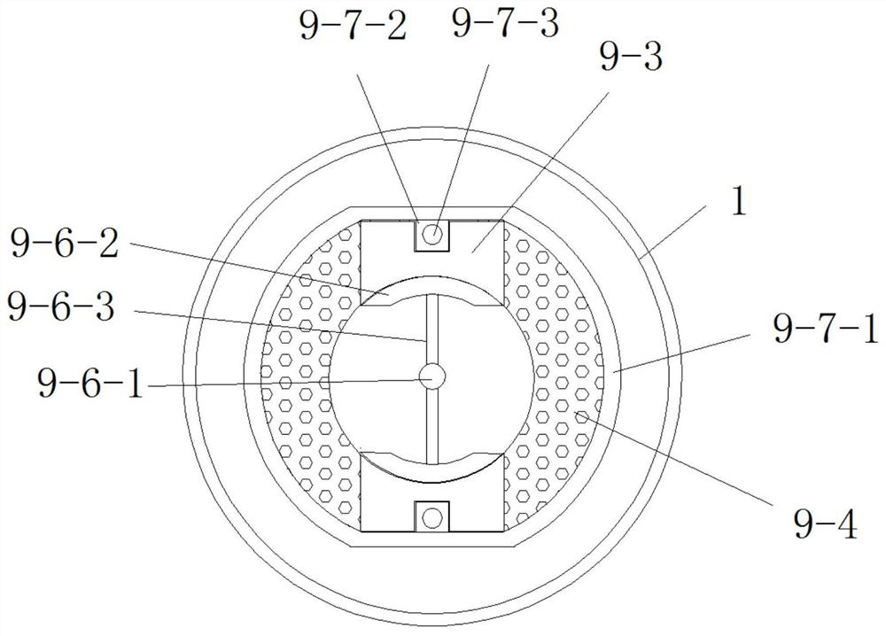
[0070] Such as Figure 2-4 As shown, the internal blocking member for a mechanical filter disclosed in this embodiment includes a control shaft 9-6-1, an arc-shaped piece 9-6-2 and a strut 9-6-3; the control shaft 9- One end of 6-1 is arranged on the bottom of the tank body 1 through the rotation of a rod, and the upper end of the control shaft 9-6-1 passes through the top of the tank body 1 and is connected with the adjustment dial 6. The arc piece 9-6-2 The support rod 9-6-3 is symmetrically arranged on the control shaft 9-6-1, and the outer wall of the arc-shaped sheet 9-6-2 is ...


PUM


Abstract

The invention discloses a mechanical filter, relates to the technical field of filter equipment, and aims at solving the problem that the cleaning is not complete as the existing mechanical filter cannot clean and filter at the same time and the flushing mode is single. The mechanical filter comprises tank bodies, a water inlet and outlet member, an upper-layer air intake tube, a lower-layer air intake tube, a reverse water inlet tube, a regulating turntable, a lifting motor, a blow-off tube and a filtering member; the tank bodies are symmetrically arranged through a support rod, the tank bodies are connected through a water inlet and outlet member, the upper-layer air intake tube, the lower-layer air intake tube and the reverse water inlet tube are arranged on the outer side wall of the tank body, the regulating turntable is arranged at the upper end of the tank body, the lifting motor and the blow-off tube are arranged at the lower end of the tank body, and the filtering member is arranged at the inner part of the tank body. The mechanical filter solves the problem that the cleaning is not complete as the existing mechanical filter cannot clean and filter at the same time and theflushing mode is single, and the effects of uninterruptedly filtering and completely self-cleaning are achieved.

Description

technical field [0001] The invention relates to the technical field of filtering equipment, in particular to a mechanical filter. Background technique [0002] There are generally impurities such as colloids, fine suspended solids, and particles in natural water, and direct use in production will affect the life of the equipment and the quality of the product. Therefore, it is usually necessary to purify the water before using the above natural water so that it can meet production requirements. However, the current water purification treatment usually adopts chemical or biological treatment methods, but most of these methods are suitable for water quality treatment, such as wastewater or sewage treatment. Through chemical and biological treatment methods, harmful substances in wastewater or sewage can be treated to form a To achieve the effect of purifying water quality, but these water quality treatment methods basically have no effect on the colloidal or granular suspende...

Claims


Application Information

Patent Timeline
Patent Type & Authority Patents(China)
IPC IPC(8): B01D29/03B01D29/68
CPCB01D29/035B01D29/68
Inventor 幸蜀巍
Owner 黑龙江三幸环保科技有限公司
Why Eureka
Try Eureka