Mechanical filter
A technology of mechanical filters and tanks, which is applied in the direction of fixed filter element filters, filtration separation, chemical instruments and methods, etc., and can solve problems such as single filtering and washing methods, incomplete cleaning, and inability to clean mechanical filters at the same time
- Summary
- Abstract
- Description
- Claims
- Application Information
AI Technical Summary
Problems solved by technology
Method used
Image
Examples
specific Embodiment approach 1
[0053] This embodiment is a mechanical filter embodiment.
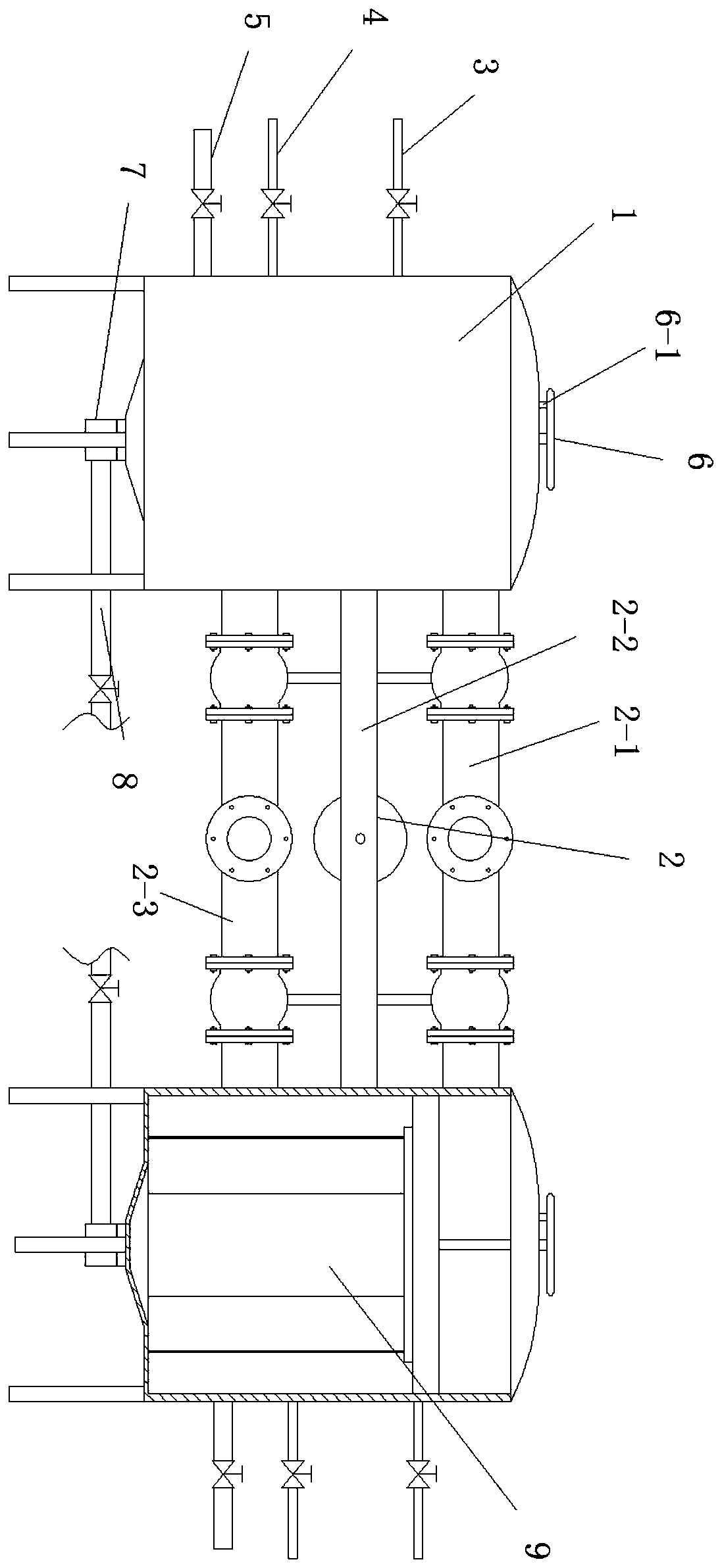
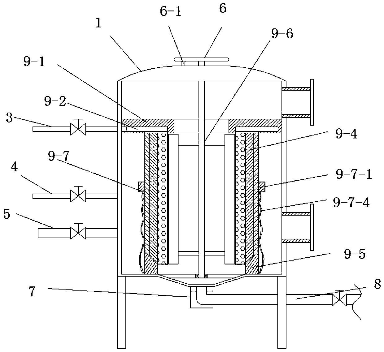
[0054] Such as Figure 1-5 As shown, a mechanical filter disclosed in this embodiment includes a tank body 1, water inlet and outlet components 2, upper air intake pipe 3, lower air intake pipe 4, reverse water inlet pipe 5, adjusting dial 6, lifting motor 7, and sewage pipe 8 and filter member 9; the tank body 1 is arranged symmetrically through the support rods, and the tank body 1 is connected by the water inlet and outlet components 2, and the upper air intake pipe 3, the lower air intake pipe 4 and the reverse air intake pipe 4 are arranged on the outer wall of the tank body 1 The water inlet pipe 5, the upper end of the tank body 1 is provided with an adjusting dial 6, the lower end of the tank body 1 is provided with a lifting motor 7 and a sewage pipe 8, and the inside of the tank body 1 is provided with a filter member 9;
[0055]Close the valves on the upper floor air intake pipe 3, the lower floor air inta...
specific Embodiment approach 2
[0064] This embodiment is an embodiment of an arc-adjusting filter layer.
[0065] It should be noted that the arc-shaped filter layer in this embodiment can be implemented independently, that is, it can exist independently as a part of a mechanical filter, and it can also be further limited to the mechanical filter described in the first embodiment.
[0066] combine Figure 5 As shown, the arc-shaped filter layer facing the filter member disclosed in this embodiment includes an arc-shaped net cover 9-4-1, an arc-shaped net 9-4-2 and a filter medium 9-4-3, and the arc-shaped net cover 9 The upper wall of -4-1 is set in the annular groove 9-2 of the annular plate 9-1, and the upper wall of the arc net cover 9-4-1 has a through hole, and the arc net cover 9-4-1 The lower wall is arranged on the bottom of the inner wall of the tank body 1 through the arc retaining strip 9-5, the side wall of the arc net cover 9-4-1 is arranged on the side wall of the vertical beam 9-3, and the a...
specific Embodiment approach 3
[0069] This embodiment is an embodiment of an internal blocking member for a mechanical filter. It should be noted that the internal blocking member for a mechanical filter of this embodiment can be implemented separately, that is, it can exist alone as a part of a mechanical filter, and it can also be used for a mechanical filter described in the first embodiment. The device is further limited.
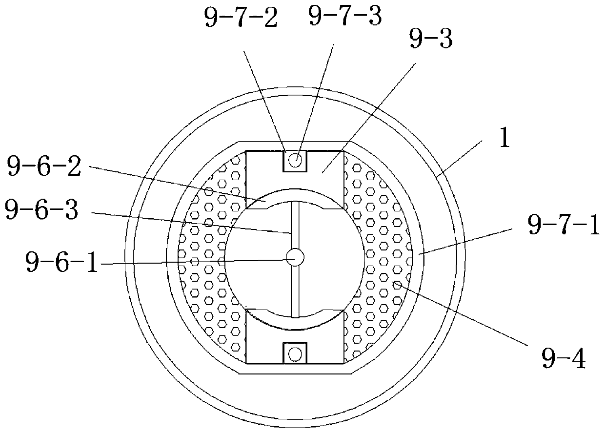
[0070] Such as Figure 2-4 As shown, the internal blocking member for a mechanical filter disclosed in this embodiment includes a control shaft 9-6-1, an arc-shaped piece 9-6-2 and a strut 9-6-3; the control shaft 9- One end of 6-1 is arranged on the bottom of the tank body 1 through the rotation of a rod, and the upper end of the control shaft 9-6-1 passes through the top of the tank body 1 and is connected with the adjustment dial 6. The arc piece 9-6-2 The support rod 9-6-3 is symmetrically arranged on the control shaft 9-6-1, and the outer wall of the arc-shaped sheet 9-6-2 is ...
PUM
 Abstract
Description
Claims
Application Information
 - R&D
- Intellectual Property
- Life Sciences
- Materials
- Tech Scout
- Unparalleled Data Quality
- Higher Quality Content
- 60% Fewer Hallucinations
Browse by: Latest US Patents, China's latest patents, Technical Efficacy Thesaurus, Application Domain, Technology Topic, Popular Technical Reports.
© 2025 PatSnap. All rights reserved.Legal|Privacy policy|Modern Slavery Act Transparency Statement|Sitemap|About US| Contact US: help@patsnap.com


