Magnetic Field Coupled Wave Energy Harvester

An energy harvester and magnetic field coupling technology, which is applied in the control of mechanical energy, ocean energy power generation, machine/engine, etc., can solve the problem of low output power, achieve the effect of increasing output power, novel structure, and overcoming low output power

CN110107446BActive Publication Date: 2020-08-18HUNAN INSTITUTE OF ENGINEERING
10 Cites 0 Cited by

Patent Information

Authority / Receiving Office
CN · China
Patent Type
Patents(China)
Current Assignee / Owner
Publication Date
2020-08-18

Smart Images

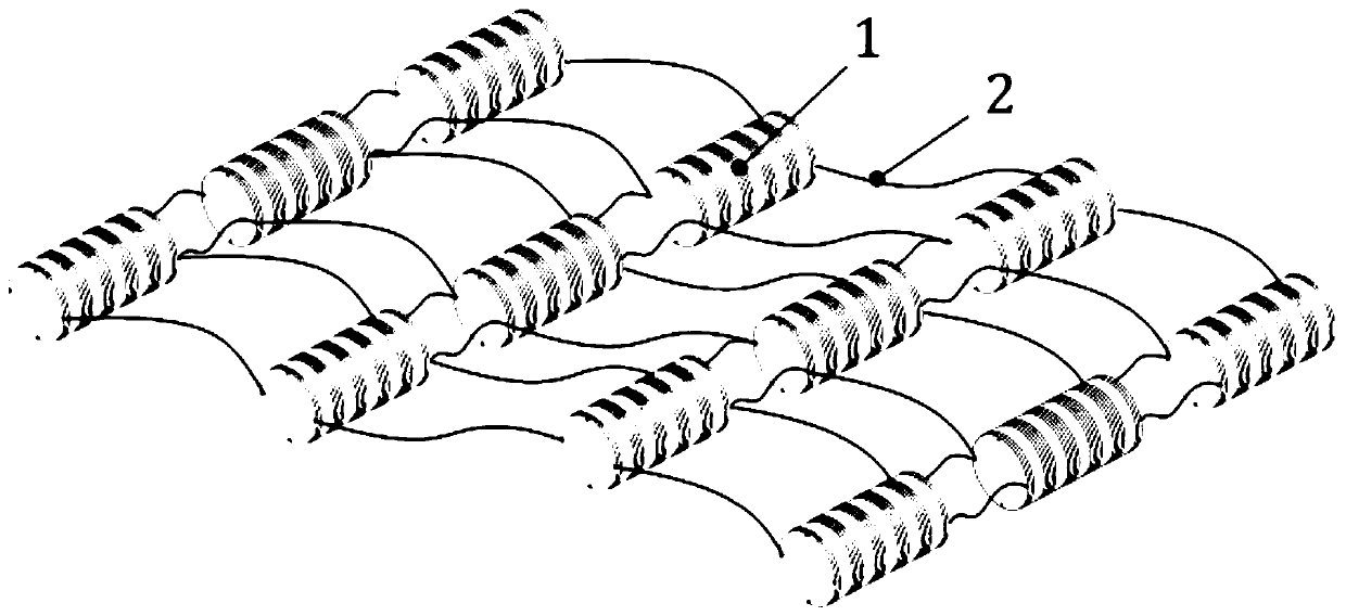
  • Figure 1
    Figure 1
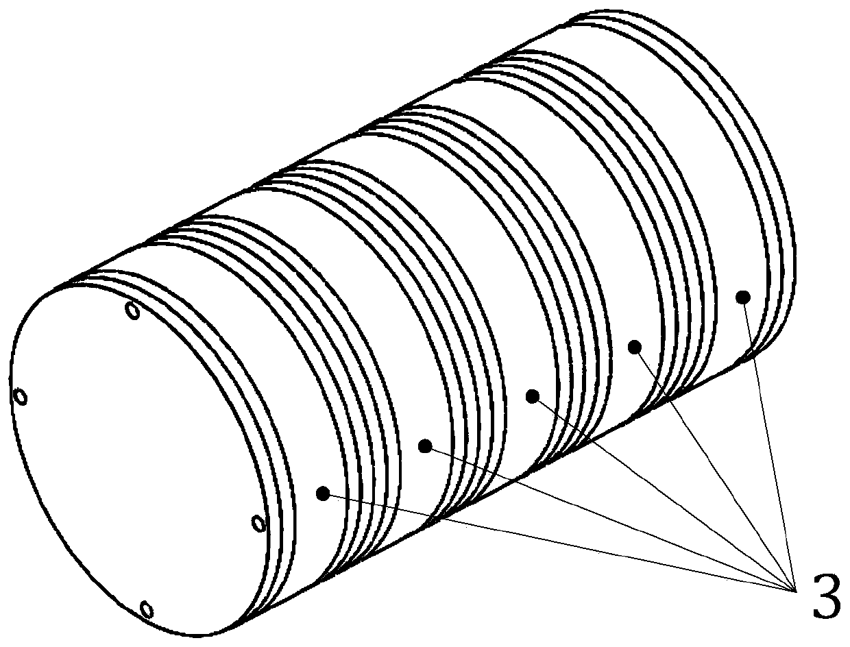
  • Figure 2
    Figure 2
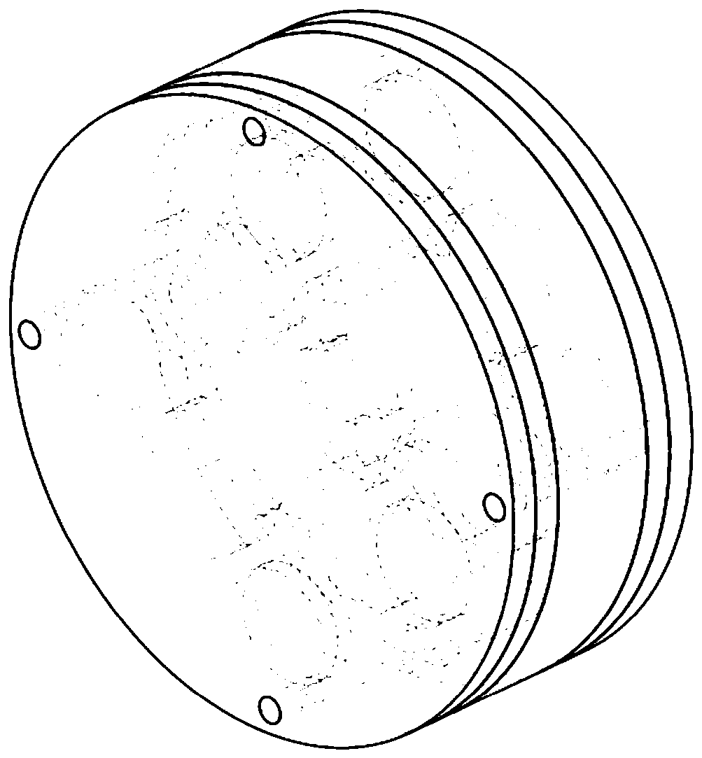
  • Figure 3
    Figure 3
Patent Text Reader

Abstract

The invention relates to a magnetic field coupling wave energy collector which comprises multiple magnetic coupling unit assemblies and a rope. The multiple magnetic coupling unit assemblies are connected through the rope and are arranged in an array way; the magnetic coupling unit assemblies are formed by side-by-side superimposing multiple magnetic coupling units aligned in centers in an array way; the magnetic coupling units comprise movable magnets, and anti-magnet pyrolytic graphite plates, magnetism adjusting parts and electricity generation parts symmetrically arranged on two sides of the movable magnets; the movable magnets are cylindrical permanent magnets; the magnetic pole directions of the movable magnets are thickness directions; the movable magnets are built in a rolling springback rail and are consistent to a thickness direction of the rolling springback rail; the rolling springback rail is embedded into an outer sleeve and is coaxial to the outer sleeve; and the anti-magnet pyrolytic graphite plates are arranged on two sides of the rolling springback rail and are embedded into the outer sleeve. Compared with the prior art, the magnetic field coupling wave energy collector provided by the invention can be beneficial to improving the output power, can effectively work under microwave, adapts to multi-directional wave excitation, and overcomes the defect of low output power of an existing small wave energy collector.
Need to check novelty before this filing date? Find Prior Art

Description

[technical field]

[0001] The invention relates to the technical field of energy collection, in particular to a magnetic field coupled wave energy collector. [Background technique]

[0002] With the rapid development of new materials, micro-nano manufacturing and integrated electronics, the energy consumption of electronic devices has been greatly reduced, and the use of energy harvesting technology to effectively supply energy for micro-electromechanical systems for a long time has become a hot research topic at home and abroad. More than 70% of the earth's surface is covered by water, and wave energy is widely distributed all over the world, and it is one of the most abundant energy sources that can be applied on a large scale.

[0003] Wave energy has little dependence on day or night, so it can be continuously and efficiently converted into electricity. Converting ocean wave energy into electrical energy can realize self-powered sensing, control, and drive of the ocean e...

Examples

Embodiment Construction

[0022] Below in conjunction with accompanying drawing, the present invention will be further described as follows:

[0023] As shown in the accompanying drawings, the present invention includes several magnetic coupling unit combinations 1 and ropes 2, a plurality of magnetic coupling unit combinations 1 are connected by ropes 2 and arranged in an array, and the magnetic coupling unit combination 1 consists of several center-aligned magnetic coupling units 3 stacked side by side in an array, the magnetic coupling unit 3 includes a moving magnet 4, a diamagnetic pyrolytic graphite plate 5, a magnetic adjustment component 6 and a power generation component 7, and the diamagnetic pyrolytic graphite plate 5, the magnetic force adjustment component 6 and the power generation component 7 are symmetrically arranged On both sides of the moving magnet 4 , antimagnetic pyrolytic graphite plates 5 , magnetic adjustment components 6 , and power generation components 7 are arranged sequenti...