A hand-held screwdriver

A screw-driving, hand-held technology, applied in the field of hand-held screw-driving devices, can solve problems such as low screw-driving efficiency, hand injuries, and many manpower, and achieve the effect of saving manpower and improving efficiency

Active Publication Date: 2021-09-07
无锡品知信息科技有限公司
View PDF0 Cites 0 Cited by
  • Summary
  • Abstract
  • Description
  • Claims
  • Application Information

AI Technical Summary

Problems solved by technology

[0005] In order to overcome the current disadvantages that people tend to injure their hands when screwing screws, consume more manpower, and have lower screw screwing efficiency, the technical problem is to provide a hand-held screw screwing device that can save manpower, is safe, and has high efficiency.

Method used


Image

  • A hand-held screwdriver
  • A hand-held screwdriver
  • A hand-held screwdriver

Examples


Embodiment 1

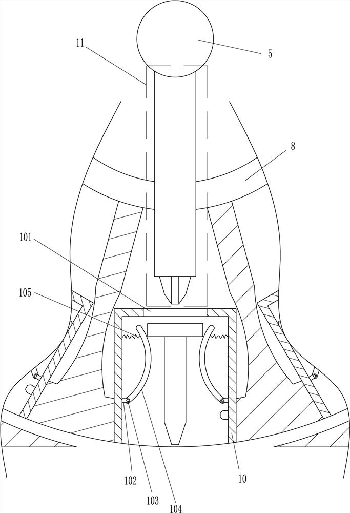
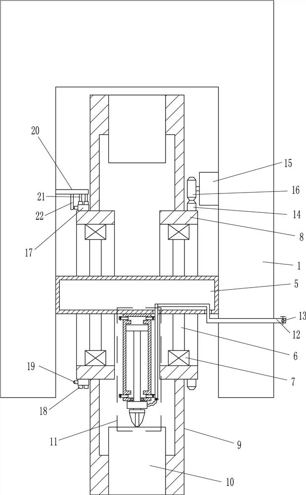
[0026] A handheld screwdriver, such as figure 1 , figure 2 , image 3 , Figure 4As shown, it includes a hand grip 1, an external hose 2, a first switch 3, a second switch 4, a middle round box 5, an extension rod 6, a bearing seat 7, a rotating ring 8, a connecting ring frame 9, and a storage box 10 , shaft seat 102, rotating shaft 103, arc rod 104, spring 105, impact screwing device 11, connecting air pipe 12, first electric control valve 13, first gear 14, servo motor 15, second gear 16, mounting plate 17 , receiving coil 18, contact switch 19, connecting block 20, electrode 21 and bump 22, the right side of hand-held device 1 is connected with external hose 2, and external hose 2 is provided with power cord and external trachea, hand-held The lower side of the middle part of the device 1 is connected with a first switch 3, and the upper side of the middle part of the handheld device 1 is connected with a second switch 4. The second switch 4 is a three-speed switch, and...

Embodiment 2

[0029] On the basis of Example 1, such as Figure 5 As shown, the impact screwing device 11 includes a cylinder 111, a piston 112, a push rod 113, a sealing ring 114, an air motor 115, a screw head 116, a tap pipe 117, a second electric control valve 118, a connecting air hose 119, The first air intake pipe 1110, the third electric control valve 1111, the second air intake pipe 1112, the fourth electric control valve 1113, the first exhaust pipe 1114, the fifth electric control valve 1115, the second exhaust pipe 1116 and the sixth electric Control valve 1117, a cylinder 111 is connected in the middle of the bottom of the middle circular box 5, a piston 112 is arranged in the cylinder 111, a push rod 113 is connected in the middle of the top of the piston 112, a sealing ring 114 is embedded in the middle of the bottom of the cylinder 111, and the push rod 113 wears Through the sealing ring 114, the bottom end of the push rod 113 is connected with the air motor 115, and the pus...

Embodiment 3

[0032] On the basis of Example 2, such as figure 1 , image 3 , Figure 6 , Figure 7 , Figure 8 As shown, a metal detector 301 and an indicator light 302 are also included. The metal detector 301 is connected to the right side of the placement box 10. The metal detector 301 is located under the shaft seat 102. The front side of the placement box 10 is connected to an indicator light 302. , the metal detector head 301 and the indicator light 302 are connected to the control module through lines.

[0033] Also include a first connecting rod 311, an upper protective cover 312, a second connecting rod 314 and a lower protective cover 315, the upper left side of the hand grip 1 is connected with the first connecting rod 311, the bottom left of the first connecting rod 311 The side is connected with an upper protective cover 312, the first connecting rod 311 is connected with the upper protective cover 312 by means of bolt connection, the right part of the upper protective cov...


PUM


Abstract

The invention relates to a screw-driving device, in particular to a hand-held screw-driving device. Technical problem: Provide a hand-held screw-driving device that can save manpower, is safe, and has high efficiency. The technical solution is: a hand-held screw-tightening device, including a hand-held device, an external hose, an intermediate round box, etc.; the right side of the hand-held device is connected with an external hose, and the external hose is provided with a power cord and an external air pipe . In the present invention, by pushing the screw into the storage box, under the action of the spring, the arc-shaped rods on the left and right sides can clamp the screw, which can make screwing more convenient and fast; the connecting ring frame can be driven to rotate by the servo motor , so as to drive the placement box to rotate, so that the placement box can be rotated one by one to the right below the impact screw-in device; through the impact screw-in device, the screws in the placement box can be screwed to the desired position, thereby saving manpower and improving screw screwing efficiency .

Description

technical field [0001] The invention relates to a screw-driving device, in particular to a hand-held screw-driving device. Background technique [0002] The screw is a tool for tightening the parts of the object step by step by using the physical and mathematical principles of the oblique circular rotation and friction of the object. [0003] In the process of building construction, people often need to use screws to fix materials. At present, people often use screwdrivers to screw screws. Sometimes slipping occurs during the screw screwing process, which causes people's hands to be injured, and some materials It is relatively hard, and it is difficult to screw in the screws, which requires more manpower. In this way, people will use an electric screwdriver to complete it. When using an electric screwdriver to screw the screws, they need to place the screws one by one by hand. The efficiency of screwing. [0004] Therefore, it is necessary to develop a hand-held screw-twis...

Claims


Application Information

Patent Timeline
Patent Type & Authority Patents(China)
IPC IPC(8): B23P19/06
CPCB23P19/001B23P19/006B23P19/06
Inventor 周朋
Owner 无锡品知信息科技有限公司
Why Eureka
Try Eureka