Tensile reinforced concrete chute lining structure

A reinforced concrete, tensile-type technology, which is applied in the field of mine shaft engineering, can solve problems such as poor effect, accelerated shaft deformation and damage, and fast wear speed, and achieves a remarkable tensile effect, eliminating bonding, and strong practicability Effect

Inactive Publication Date: 2019-09-27
铜陵有色金属集团股份有限公司 +1
View PDF9 Cites 0 Cited by
  • Summary
  • Abstract
  • Description
  • Claims
  • Application Information

AI Technical Summary

Problems solved by technology

In order to improve the impact resistance and wear resistance of concrete in some mines, reinforced concrete reinforcement is still not effective, but it is more likely to cause ore to block the shaft and wear faster
Existing studies have shown that the failure of the chute is mostly tensile (shear) failure, while the tensile and shear resistance of plain concrete is low. Under the influence of surrounding rock fragmentation, expansion pressure, and insufficient filling of the void behind the wall, the plain poured well wall is easily damaged. shear and tensile failure
Although many mines use steel rails and (high) manganese steel plates to increase the strength of the shaft wall at the impact point, these rails and steel plates are often fixed by spot welding, and their fixing strength is low
Even if fixed methods such as anchors or rooting hooks are used, it is still easy to crack and fall off after being subjected to strong impact and vibration, and even cause side effects such as blockage of the chute, which accelerates the deformation and destruction of the wellbore
High-manganese steel plates have poor weldability and reworkability, high reinforcement costs, and labor-intensive installation and handling. They are generally used in large mines
However, the application cases and experience of new reinforcement technologies such as rubber lining, steel fiber sprayed concrete, resin concrete manganese steel plate, and rare earth wear-resistant steel reinforcement are insufficient, and further exploration and practice are still needed.

Method used


Image

  • Tensile reinforced concrete chute lining structure
  • Tensile reinforced concrete chute lining structure
  • Tensile reinforced concrete chute lining structure

Examples


Embodiment 1

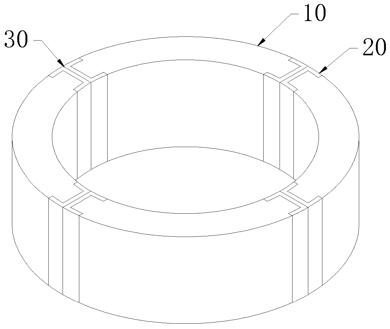
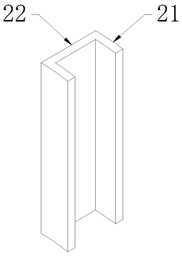
[0030] like Figure 1~3 As shown, a tensile reinforced concrete chute lining structure includes several lining units 10 of a reinforced concrete structure connected head to tail to form a ring and steel channels 20 arranged at both ends of the lining unit 10. The lining unit 10 is Arc-shaped, and the lining unit 10 is provided with a steel cage skeleton 11, the steel channel 20 includes an integrated back plate 22 and guard plates 21 on both sides of the back plate 22, the back plate 22 and the guard plate 21 are "[" shape, the back plates 22 of adjacent steel channels 20 are close to each other, and deformation seams 30 are formed between the back plates 22 of adjacent steel channels 20 .

[0031] In this embodiment, the lining unit 10 is prefabricated reinforced concrete. During construction, it is only necessary to hoist the lining unit 10 to a designated installation location, and after the steel channels 20 are clamped at both ends, they are assembled into a ring-shaped c...

Embodiment 2

[0035] like Figure 4 As shown, the difference between this embodiment and Embodiment 1 is that the lining unit 10 and the steel channel 20 are an integral prefabricated structure, and the steel channel 20 and the reinforcement cage frame 11 inside the lining unit 10 are welded and fixed during prefabrication. In this way, the splicing and fixing of the steel channel 20 and the lining unit 10 can be realized during prefabrication, and the assembly operation of the steel channel 20 and the lining unit 10 can be omitted when the lining is installed in the chute, which greatly improves the installation efficiency and improves the steel channel. 20 and the connection strength and stability of the lining unit 10.

Embodiment 3

[0037] like Figure 5 As shown, the difference between this embodiment and Embodiment 2 is that: the main body of the lining unit 10 is provided with a grouting hole 12, and the grouting hole 12 extends to the back of the lining unit 10 in contact with the chute wall.

[0038] The purpose of reserving the grouting hole 12 is that after the lining structure is formed, grouting behind the wall can be carried out through the grouting hole 12, and even the plastic area of ​​the surrounding rock can be grouted, so as to densely fill the gap behind the wall and strengthen the weak surrounding rock, so that the lining It is integrated with the surrounding rock for joint load, so it has the advantages of increasing the equivalent thickness of the lining, improving the waterproof condition of the lining, and loosening the rock mass after stabilizing the wall. In addition, when the lining unit 10 is prefabricated, the grouting hole 12 is easy to leave , will not affect the lining streng...


PUM


Abstract

The invention discloses a tensile reinforced concrete chute lining structure which comprises a plurality of lining units and steel grooves. The lining units are connected end to end to form a ring-shaped reinforced concrete structure, the steel grooves are arranged at the two ends of the lining units, the lining units are in an arc shape, a reinforcement cage framework is arranged in the lining units, each steel groove comprises an integrated back plate and guard plates on the two sides of the back plate, the back plates of every two adjacent steel grooves abut against each other, and a deformation joint is formed between the back plates of every two adjacent steel grooves. The traditional stress concept of the lining is changed, concrete and steel bars in the lining separately work and stress, the pressure bearing performance of the concrete and the tensile performance of the steel bars are exerted, the tensile effect of the lining is remarkable, and construction is convenient.

Description

technical field [0001] The invention belongs to the technical field of mine chute engineering, in particular to a tensile-type reinforced concrete chute lining structure. Background technique [0002] The chute is a mine tunnel project that uses its own weight to slide ore from top to bottom. It is used as a throat project for underground metal mines to store and transport ore rocks. Whether it is stable or not will directly affect the normal production of the mine. In the process of production and use, due to engineering geological conditions, linkage damage effect of group wells, excessive ore unloading impact load, insufficient shaft support strength and other reasons, the slide shafts have different degrees of wear and tear or even collapse, which seriously restricts the safe and stable production of mines. . At present, the reinforcement and support forms of domestic mine shafts mainly include plain (reinforced) concrete, steel rails, (manganese) steel plates, high man...

Claims


Application Information

Patent Timeline
Patent Type & Authority Applications(China)
IPC IPC(8): E21F13/04
CPCE21F13/04
Inventor 卫明蒋志明彭泽锋余茂杰刘强邓琛胡敏罗皖东张见苏广宇
Owner 铜陵有色金属集团股份有限公司
Why Eureka
Try Eureka