Concrete vibrator

A vibrator and concrete technology, which is applied in the fields of construction, building structure, and building materials, can solve the problems of slow pulling out, achieve the effect of improving the vibrating efficiency and ensuring the vibrating quality

Inactive Publication Date: 2019-10-11
湖北乾奥建设工程有限公司
View PDF0 Cites 9 Cited by
  • Summary
  • Abstract
  • Description
  • Claims
  • Application Information

AI Technical Summary

Problems solved by technology

But for concrete vibrating, the vibrating rod should be inserted quickly and pulled out slowly, so as not to leave voids in the concrete, but the existing vibrating rods cannot meet this requirement

Method used


Image

  • Concrete vibrator

Examples


Embodiment Construction

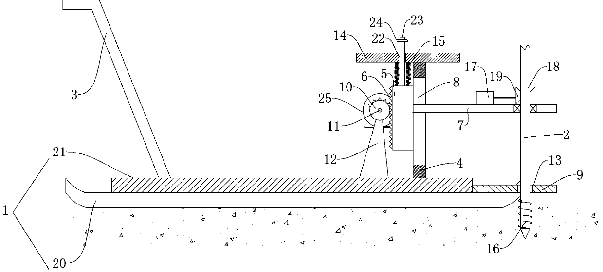
[0017] Such as figure 1 As shown, a concrete vibrator includes a supporting platform 1 and a vibrating rod 2. The supporting platform 1 is provided with a push handle 3 and a lifting device, and the lifting device includes a vertically arranged slide rail 4. Inside the slide rail 4 A slider 5 is provided, one side of the slider 5 is provided with a rack 6, and the other side is provided with a transverse first cantilever plate 7, and the side of the slide rail 4 away from the rack 6 is provided with a first cantilever plate 7 The vertical channel 8 that moves up and down, the first cantilever plate 7 is provided with a vibrating rod 2 vertically arranged, the rack 6 is meshed with the half gear 10, the half gear 10 is sleeved on the rotating shaft 11, and the rotating shaft 11 Rotation is installed on the rotating shaft frame 12, the rotating shaft 11 is driven to rotate by the first driving device 25, the top of the slide rail 4 is provided with a horizontal limiting plate 14...


PUM


Abstract

The invention provides a concrete vibrator which comprises a supporting platform and a vibrating rod. A push handle and a lifting device are arranged on the supporting platform, the lifting device comprises a vertically arranged slide rail, a slide block is arranged in the slide rail, a rack is arranged on one side of the slide block, a transverse first cantilever plate is arranged on the other side, a vertical slot where the first cantilever plate moves up and down is formed in the side, far away from the rack, of the slide rail, the vertically arranged vibrating rod is arranged on the firstcantilever plate, the rack is engaged to a half gear, the half gear is mounted on a rotary shaft in a sleeving manner, the rotary shaft is rotatably mounted on a rotary shaft rack, the rotary shaft isdriven by a first driving device to rotate, a horizontal limiting plate is arranged at the top end of the slide rail, a sliding through hole is formed in the horizontal limiting plate, a sliding baris arranged on the top of the slide block, the upper end of the slide bar penetrates the sliding through hole, and a limiting block is arranged at the upper end of the slide bar. The vibrator can meetthe demand that the vibrator is inserted into concrete quickly and is pulled out of the concrete slowly, and meanwhile, the vibrator is relatively high in vibrating efficiency and guarantees the quality of a concrete member.

Description

technical field [0001] The invention belongs to the field of building construction, in particular to a concrete vibrator. Background technique [0002] Vibration refers to the process of vibrating and compacting the concrete unloaded into the pouring bin to improve its strength and ensure the quality of concrete components. Vibration can eliminate the air bubbles in the concrete, make the concrete densely combined, eliminate the phenomenon of concrete honeycomb pitting, so as to improve its strength and ensure the quality of concrete components. [0003] Existing internal vibrators generally use vibrating rods, which require hand-held operation by construction personnel, and the efficiency is low. While operating with related auxiliary devices, the vibrator uses a motorized device to drive the vibrator to insert or pull out the concrete while vibrating, and the speed of insertion and removal is the same. But for concrete vibration, the vibrating rod should be fast when ins...

Claims


Application Information

Patent Timeline
Patent Type & Authority Applications(China)
IPC IPC(8): E04G21/08
CPCE04G21/08
Inventor 李富曹涛李禹峰石涛
Owner 湖北乾奥建设工程有限公司
Why Eureka
Try Eureka