Inserting type vibration device

A vibrating device and plug-in technology, applied in construction, building structure, construction material processing and other directions, can solve the problems of high labor cost, difficult application, high labor intensity, etc.

Pending Publication Date: 2021-05-28
HUNAN WUXIN MACHINERY
View PDF0 Cites 0 Cited by
  • Summary
  • Abstract
  • Description
  • Claims
  • Application Information

AI Technical Summary

Problems solved by technology

[0002] In the concrete vibrating process in the construction of concrete pavement or floor, the current common practice is still to use a hand-held plug-in vibrator for vibrating. During the operation, the operator needs to repeatedly extract the vibrating rod from the concrete and insert it into the concrete. Medium, high labor intensity, high labor cost and low construction efficiency
There are also row-by-row lift-type vibrating devices, where the plug-in vibrators are installed side by side in a row, and are driven up and down at the same time by an integrated drive to realize the action of inserting and pulling out concrete, which can alleviate the aforementioned problems to a certain extent, but This method is difficult to apply when the depth of the concrete to be constructed is different (such as the tunnel invert layer and the filling layer, the bottom surface of which is curved)

Method used


Image

  • Inserting type vibration device
  • Inserting type vibration device
  • Inserting type vibration device

Examples


Embodiment 1

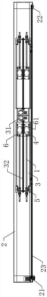
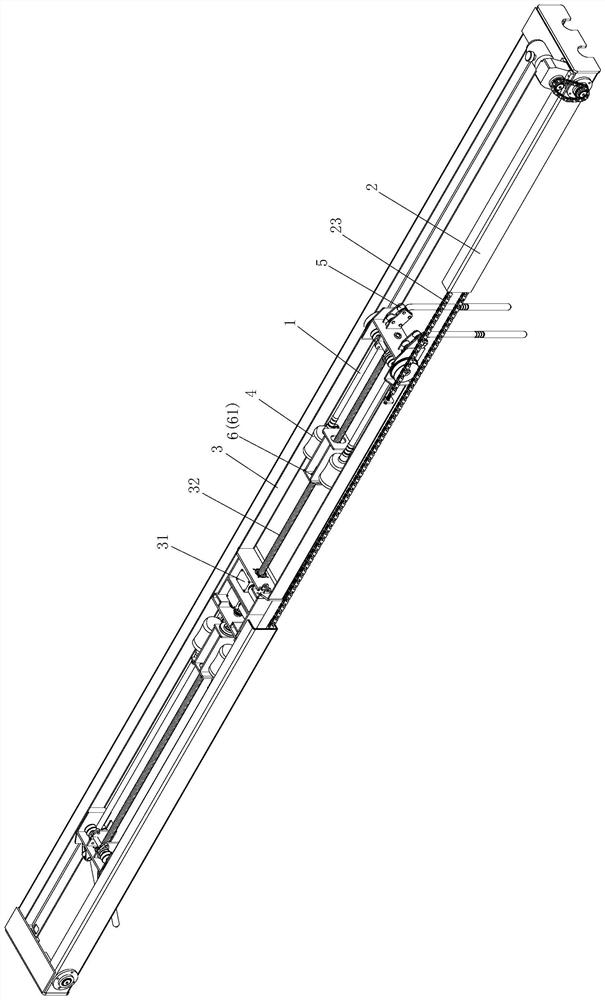
[0026] Figure 1 to Figure 4 An embodiment of the plug-in vibrating device of the present invention is shown. The plug-in vibrating device of this embodiment includes a vibrating rod 1, a track frame 2 and a mobile trolley 3 arranged on the track frame 2, and the mobile trolley 3 There is a vibrating driver 4, a vibrating rod guide 5, and a vibrating trolley 6 for driving the vibrating driving part 4 to reciprocate. The vibrating rod 1 is connected with the vibrating driving part 4, and the vibrating driving part 4 Set on the vibrating trolley 6. Wherein, the vibrator bar guide 5 can be, for example, a pair of guide wheels, and the vibrator 1 is sandwiched between the pair of guide wheels, and the vibrator driver 4 can be, for example, a common vibrator motor etc.; Horizontally arranged, correspondingly, the mobile trolley 3 and the vibrating trolley 6 both move laterally. Wherein, the vibrator guide 5 can be a pair of guide wheels, and the vibrator 1 is sandwiched between t...

Embodiment 2

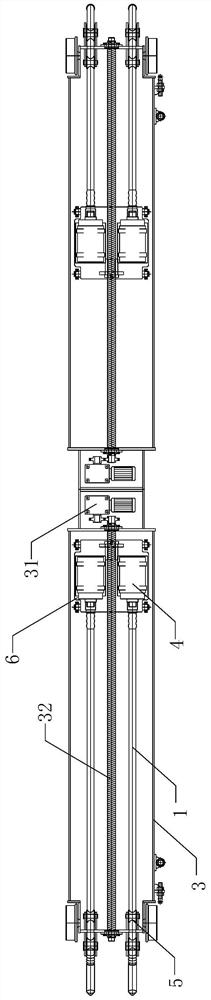
[0034] Figure 5 to Figure 6 Another embodiment of the plug-in vibrating device of the present invention is shown. The plug-in vibrating device of this embodiment is basically the same as the first embodiment, the difference is that in this embodiment, two One mobile trolley 3, two mobile trolleys 3 are arranged in parallel, and the vibrating rods 1 on the two mobile trolleys 3 face opposite. The front and rear sides of the track frame 2 can be vibrated simultaneously, which is conducive to improving construction efficiency and is suitable for concrete construction surfaces with large longitudinal dimensions.

[0035]Further, in this embodiment, the track frame 2 is provided with a mobile trolley drive assembly, and the mobile trolley drive assembly includes a driving sprocket 21, a driven sprocket 22, and a driving sprocket 21 and a driven sprocket 22. The chain 23 of two mobile dollies links to each other, and one of them mobile dolly 3 links to each other with chain 23. S...

Embodiment 3

[0037] Figure 7 Another embodiment of the plug-in vibrating device of the present invention is shown. The plug-in vibrating device of this embodiment is basically the same as that of Embodiment 1, the difference is that there are two vibrating rods 1, two vibrating rods The tampering rods 1 are arranged in parallel, and two adjacent vibrating rods 1 are facing oppositely. Correspondingly, two vibrating dollys 6 are arranged on the mobile trolley 3, and each vibrating dolly 6 is provided with a vibrating driving member 4, each The vibrating driving member 4 is connected to each vibrating rod 1 in a one-to-one correspondence. Of course, in other embodiments, the number of vibrating rods 1 can be further increased. In this embodiment, only one mobile trolley 3 is provided to realize simultaneous vibration at the left and right ends of the track frame 2 . Each vibrating trolley 6 can carry its own driving device to realize lateral movement, and also can adopt the sprocket drive ...


PUM


Abstract

The invention discloses an inserting type vibration device. The inserting type vibration device comprises a vibration rod, a vibration driving part, a vibration rod guiding part and a vibration trolley used for driving the vibration driving part to move in a reciprocating mode, wherein the vibration rod is connected to the vibration driving part, and the vibration driving part is arranged on the vibration trolley. The inserting type vibration device has the advantages of simple structure, low cost, adjustable insertion position and depth and the like.

Description

technical field [0001] The invention relates to equipment for concrete construction, in particular to a plug-in vibrating device. Background technique [0002] In the concrete vibrating process in the construction of concrete pavement or floor, the current common practice is still to use a hand-held plug-in vibrator for vibrating. During the operation, the operator needs to repeatedly extract the vibrating rod from the concrete and insert it into the concrete. Among them, the labor intensity is high, the labor cost is high and the construction efficiency is low. There are also row-by-row lift-type vibrating devices, where the plug-in vibrators are installed side by side in a row, and are driven up and down at the same time by an integrated drive to realize the action of inserting and pulling out concrete, which can alleviate the aforementioned problems to a certain extent, but This method is difficult to apply when the depth of the concrete to be constructed is different (f...

Claims


Application Information

Patent Timeline
Patent Type & Authority Applications(China)
IPC IPC(8): E04G21/08
CPCE04G21/08
Inventor 李佑福郑怀臣贺育德毛成宝张维颂谭振超
Owner HUNAN WUXIN MACHINERY
Why Eureka
Try Eureka