Unlock instant, AI-driven research and patent intelligence for your innovation.

Method, device, equipment and storage medium for determining transmission rate

A technology of transmission rate and determination method, which is applied in the field of data transmission, can solve the problems of reduction, reduction of transmission cycle data volume, reduction of transmission cycle data transmission rate, etc., and achieve the effect of increasing transmission rate

Active Publication Date: 2021-11-12
BIGO TECH PTE LTD
View PDF3 Cites 0 Cited by
  • Summary
  • Abstract
  • Description
  • Claims
  • Application Information

AI Technical Summary

Problems solved by technology

[0003] The existing BBR algorithm will have a built-in transmission cycle when the control network is working in the bandwidth detection state. The transmission cycle accumulates 8 round-trip delays by default, which are divided into 1 gain sub-cycle, 1 loss sub-cycle and 6 smooth transmissions. There are three sub-cycles. By default, the transmission rate gain coefficient of the gain sub-cycle in this transmission cycle is 1.25, the transmission rate gain coefficient of the impairment sub-cycle is 0.75, and the transmission rate gain coefficient of the smooth transmission sub-cycle is 1. At this time, the BBR algorithm can Control sending 25% more data in the gain sub-period, and if the current network packet loss rate is greater than 25%, then the extra data sent in the gain sub-period will be completely offset by the packet loss, and it will be reduced by 25% in the loss sub-period The transmission of data reduces the overall data volume of the transmission period, resulting in the current detected network bandwidth being lower than the maximum bandwidth, which reduces the data transmission volume in the next transmission period determined according to the currently detected network bandwidth, thereby reducing each The data transmission rate of the transmission cycle, which eventually leads to a cliff-like decline in the data transmission rate in the network

Method used


Image

  • Method, device, equipment and storage medium for determining transmission rate
  • Method, device, equipment and storage medium for determining transmission rate
  • Method, device, equipment and storage medium for determining transmission rate

Examples


Embodiment 1

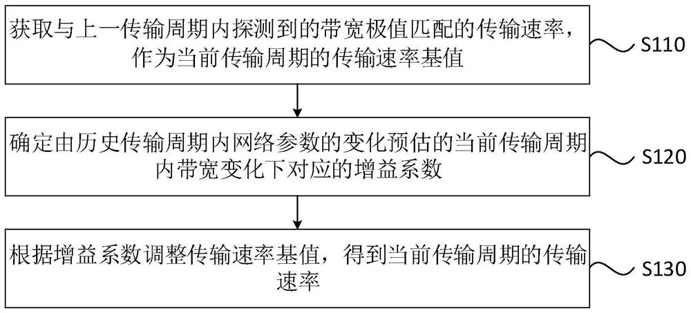
[0030] Figure 1A It is a flowchart of a method for determining a transmission rate provided by Embodiment 1 of the present invention, and this embodiment can be applied to any terminal device that sends corresponding data to other devices. A method for determining a transmission rate provided in this embodiment can be executed by the device for determining a transmission rate provided in an embodiment of the present invention. The device can be implemented by means of software and / or hardware, and integrated into a device that executes this method. , the device can be any type of terminal device capable of data transmission.

[0031] Specifically, refer to Figure 1A , the method may include the following steps:

[0032] S110. Obtain a transmission rate that matches the bandwidth extreme value detected in the previous transmission cycle, and use it as a base value of the transmission rate in the current transmission cycle.

[0033] Specifically, this embodiment mainly aims a...

Embodiment 2

[0047] Figure 2A It is a flow chart of a method for determining a transmission rate provided in Embodiment 2 of the present invention, Figure 2B It is a schematic diagram of the principle of the determination process of the transmission rate provided by Embodiment 2 of the present invention. This embodiment is optimized on the basis of the foregoing embodiments. Specifically, if the network parameters include the network packet loss rate and reception rate during data transmission, this embodiment describes in detail the specific process of determining the gain coefficient of the current transmission period based on changes in network parameters in the historical transmission period.

[0048] optional, such as Figure 2A As shown, the following steps may be included in this embodiment:

[0049] S210. Obtain a transmission rate that matches the bandwidth extreme value detected in the previous transmission cycle, and use it as a base value of the transmission rate in the cu...

Embodiment 3

[0066] Figure 3A It is a flow chart of a method for determining a transmission rate provided by Embodiment 3 of the present invention, Figure 3B It is a schematic diagram of the principle of the determination process of the transmission rate provided by Embodiment 3 of the present invention. This embodiment is optimized on the basis of the foregoing embodiments. Specifically, this embodiment mainly describes in detail the adjustment range of the first gain coefficient in the gain sub-period in the current transmission period.

[0067] optional, such as Figure 3A As shown, the following steps may be included in this embodiment:

[0068] S310. Obtain a transmission rate that matches the bandwidth extreme value detected in the previous transmission cycle, and use it as a base value of the transmission rate in the current transmission cycle.

[0069] S330. Perform filtering processing on the network packet loss rate in the historical transmission period to obtain a network ...


PUM


Abstract

The embodiment of the invention discloses a method, device, equipment and storage medium for determining a transmission rate. Among them, the method includes: obtaining a transmission rate that matches the bandwidth extremum detected in the previous transmission period, as the base value of the transmission rate of the current transmission period; determining the current transmission period estimated by the change of the network parameters in the historical transmission period The corresponding gain coefficient under the change of the internal bandwidth; adjust the base value of the transmission rate according to the gain coefficient to obtain the transmission rate of the current transmission cycle. The technical solution provided by the embodiment of the present invention adjusts the corresponding transmission rate in real time according to different network states, and does not need to use the default fixed mode transmission rate to transmit data. When transmitting data through the transmission rate of the current transmission cycle, the current The network bandwidth of the transmission cycle increases the data transmission rate.

Description

technical field [0001] The embodiments of the present invention relate to the field of data transmission, and in particular, to a method, device, device, and storage medium for determining a transmission rate. Background technique [0002] With the rapid development of Internet technology, data transmission on different devices is becoming more and more common. At this time, in order to improve the utilization rate of network bandwidth in the process of data transmission, a new congestion control algorithm (Bottleneck Bandwidth and Round-trip) is proposed. Propagation Time, BBR), the BBR algorithm can detect the maximum value of the network bandwidth and the minimum value of the round-trip delay through different working states, and then determine the data transmission rate according to the maximum value of the network bandwidth and the minimum value of the round-trip delay. Improve the utilization of network bandwidth and effectively reduce the round-trip delay of network d...

Claims


Application Information

Patent Timeline
Patent Type & Authority Patents(China)
IPC IPC(8): H04L1/00H04L12/26
CPCH04L1/0002H04L43/0876
Inventor 唐海峰朱敏刘丽石磊张威
Owner BIGO TECH PTE LTD