Reflection type laser illumination system

A laser lighting and reflective technology, applied in the field of lighting systems, can solve the problems of very high processing precision of structural parts, great influence on beam installation accuracy, difficulty in applying high-power lighting, etc., and achieve long life of laser lighting, laser light The effect of high efficiency utilization and simple wavelength conversion device

Pending Publication Date: 2019-11-26
SHANGHAI WUJING OPTOELECTRONICS SCIANDTECH CO LTD
View PDF0 Cites 0 Cited by
  • Summary
  • Abstract
  • Description
  • Claims
  • Application Information

AI Technical Summary

Problems solved by technology

[0003] A current laser lighting system, such as a laser lighting spectroscopic device disclosed in Chinese Patent Application No. 2012203086829, includes a convex lens, a light source emitter, a lens frame and a base plate, and the convex lens is installed on a far-end cover, and the far-end cover It is connected with the light source emitter through two fixed guide rods fixed on the lens frame, the distal end cover is installed on the bottom plate by screws, and a double layer is installed on the lens frame. Gaussian uniform light film, an obvious defect in this patent is that it is difficult to apply high-power lighting, low light efficiency, light beams are greatly affected by installation accuracy, high cost, and difficult to apply in large quantities; another example is the adoption of Chinese patent application No. 2011204387369 Laser lighting device for optical fiber shaping and homogenization, including a laser with a cylindrical mirror and an optical fiber section as a homogenizer; a device is provided between the cylindrical mirror and the optical fiber section for coupling the laser beam shaped by the cylindrical mirror into the optical fiber Short-focus focusing lens in the segment; it is difficult to apply high-power lighting, high installation requirements, and very low production efficiency
[0004] To sum up, the obvious defects of the current laser lighting devices and designs are that it is difficult to apply high-power lighting, low light efficiency, high installation and positioning requirements, very high precision processing of structural parts, high cost, and low production efficiency.

Method used


Image

  • Reflection type laser illumination system
  • Reflection type laser illumination system
  • Reflection type laser illumination system

Examples


Embodiment Construction

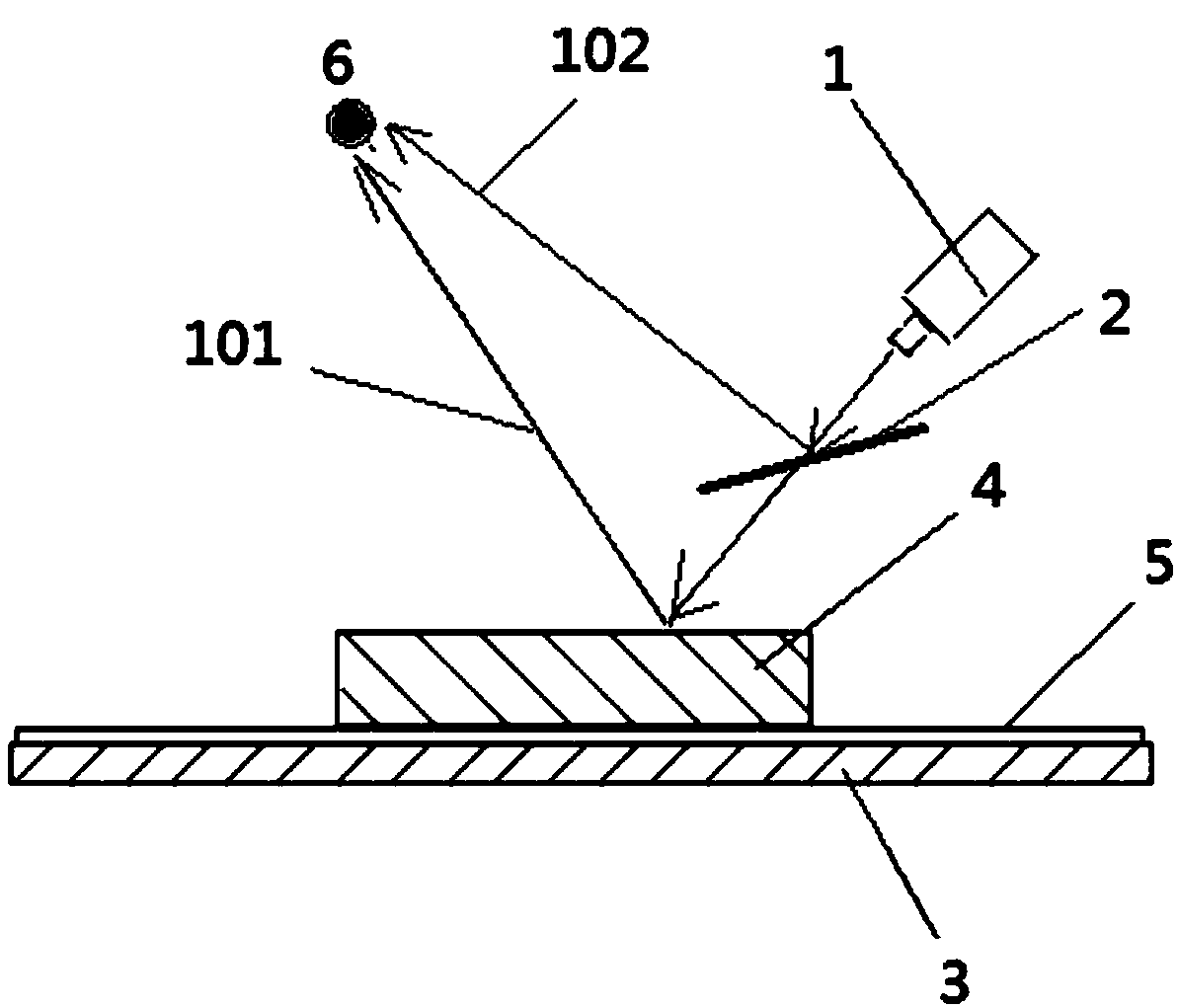
[0017] see figure 1 , the reflective laser lighting system of the present invention includes: a light source 1, a beam splitter 2, a substrate 3, a wavelength conversion layer 4 and a reflective film layer 5;

[0018] The substrate 3, the reflective film layer 5 and the wavelength conversion layer 4 are compounded sequentially;

[0019] The beam splitter 2 is arranged between the light source 1 and the wavelength conversion layer 4, the light beam emitted by the light source 1 is incident on the beam splitter 2, and the reflected beam 102 and the split light passing through the beam are obtained. After the mirror 2 shoots the wavelength conversion reflected beam 101 on the wavelength conversion layer 4, the reflected beam 102 and the wavelength conversion reflected beam 101 converge at the beam converging point 6 to obtain mixed light;

[0020] That is, the beam splitter 2 is arranged between the light source and the wavelength conversion layer, and the end point of the optic...


PUM


Abstract

The invention discloses a reflection type laser illumination system which comprises a light source, a beam splitter, a base plate, a wavelength conversion layer and a reflection film layer, wherein the base plate, the reflection film layer and the wavelength conversion layer are sequentially compounded; the beam splitter is arranged between the light source and the wavelength conversion layer; after light beams emitted from the light source are emitted onto the beam splitter, reflection light beams and wavelength conversion reflection light beams converted after the light beams pass through the beam splitter and are emitted onto the wavelength conversion layer are obtained; the reflection light beams and the wavelength conversion reflection light beams are merged in a light beam merging point; and mixed light is obtained. The functions of wavelength conversion, light reflection, light mixing, light homogenizing and the like are realized; the light efficiency is high; the irradiation distance can reach more than 10 km; and the laser illumination service life is long, is more than 5 times that of an existing mainstream illumination LED, and is more than 10 times that of a xenon lamp.

Description

technical field [0001] The present invention relates to lighting systems, in particular to laser lighting systems. Background technique [0002] Laser lighting is a new type of lighting technology that uses laser or laser diodes as light sources. It has broad application prospects in aerospace, ships, military searchlights, police lighting, search and rescue, automobiles, outdoor lighting and other fields. [0003] A current laser lighting system, such as a laser lighting spectroscopic device disclosed in Chinese Patent Application No. 2012203086829, includes a convex lens, a light source emitter, a lens frame and a base plate, and the convex lens is installed on a far-end cover, and the far-end cover It is connected with the light source emitter through two fixed guide rods fixed on the lens frame, the distal end cover is installed on the bottom plate by screws, and a double layer is installed on the lens frame. Gaussian uniform light film, an obvious defect in this patent...

Claims


Application Information

Patent Timeline
Patent Type & Authority Applications(China)
IPC IPC(8): F21K9/60F21K9/64F21K9/68F21K9/69F21Y115/30
CPCF21K9/60F21K9/64F21K9/68F21K9/69F21Y2115/30
Inventor 不公告发明人
Owner SHANGHAI WUJING OPTOELECTRONICS SCIANDTECH CO LTD
Why Eureka
Try Eureka