Driving device for realizing automatic focusing of camera

An auto-focusing and driving device technology, which is applied in the field of camera and camera focusing, can solve the problems of restricting the structure type of the driving device, failing to meet the miniaturization of products, and difficult to reduce the volume, etc., to achieve simple control, suitable for popularization and utilization, and small size Effect

Pending Publication Date: 2020-01-10
SEADEC TECH LTD
View PDF0 Cites 1 Cited by
  • Summary
  • Abstract
  • Description
  • Claims
  • Application Information

AI Technical Summary

Problems solved by technology

Due to the small space, it also limits the type of drive structure that can be used
In the existing technology, the camera mainly uses the magnet and coil structure to realize the drive, but the structure is still relatively complicated, and the volume is difficult to reduce, which cannot meet the requirements of product miniaturization.

Method used


Image

  • Driving device for realizing automatic focusing of camera
  • Driving device for realizing automatic focusing of camera
  • Driving device for realizing automatic focusing of camera

Examples


Embodiment Construction

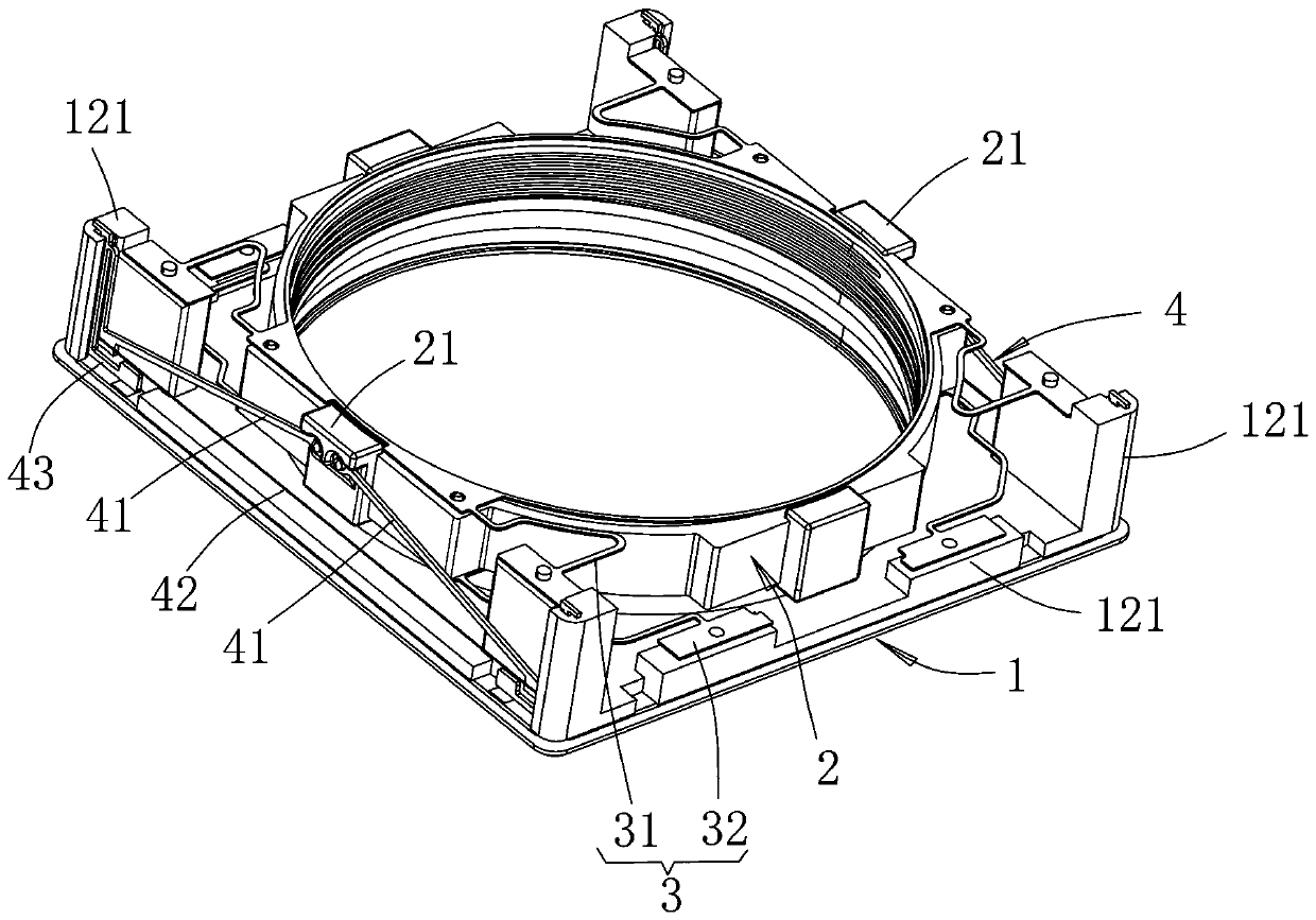
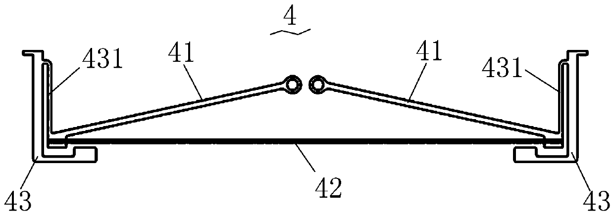
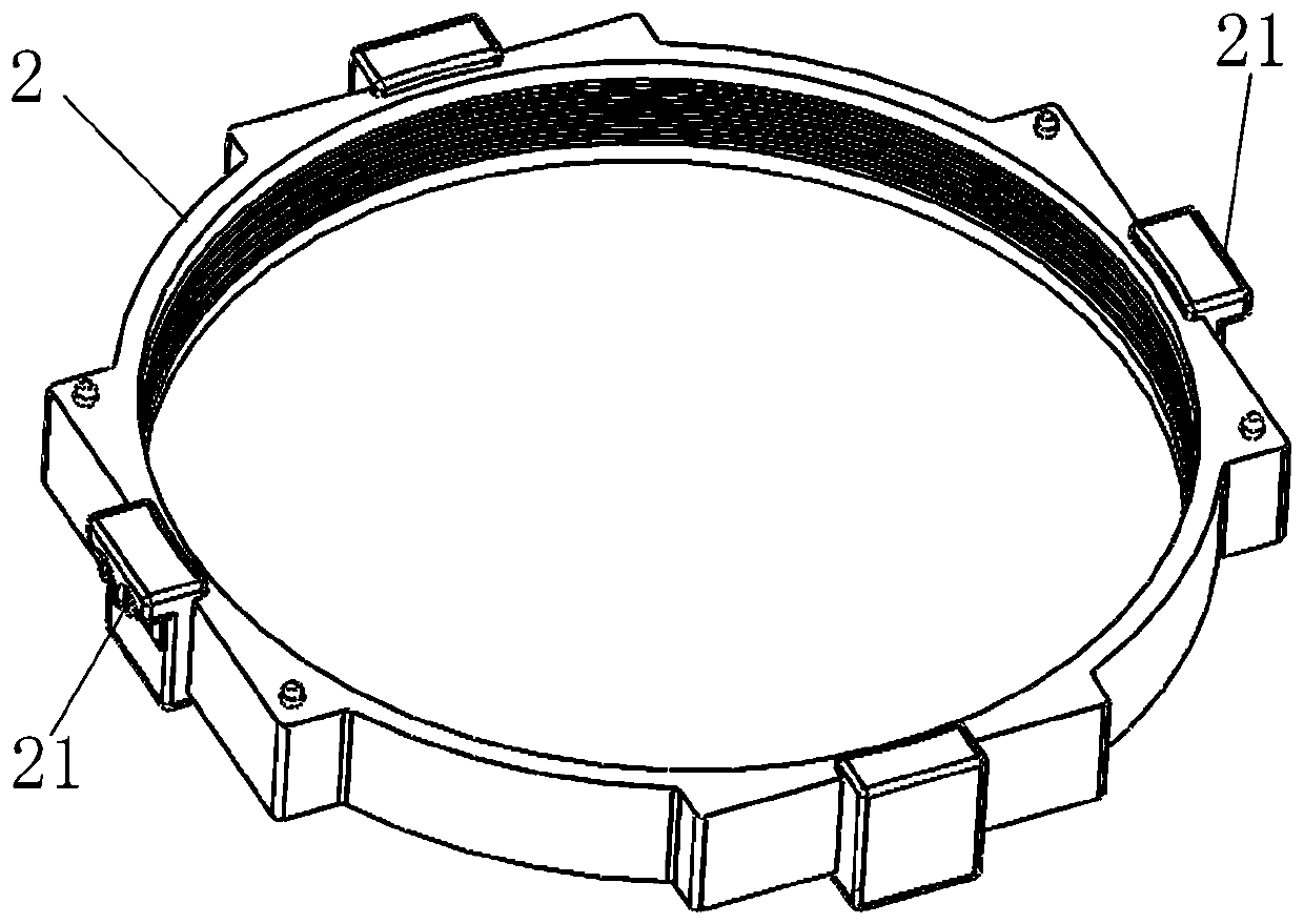
[0020] The idea, specific structure and technical effects of the present invention will be further described below in conjunction with the accompanying drawings, so as to fully understand the purpose, features and effects of the present invention.

[0021] It should be noted that, in the description of the present invention, terms such as "up", "down", "left", "right", "vertical", "horizontal", "inside", "outside" and so on indicate directions or The terms of positional relationship are based on the direction or positional relationship shown in the drawings, which are only for convenience of description, and do not indicate or imply that the device or element must have a specific orientation, be constructed and operated in a specific orientation, and therefore cannot be understood To limit the present invention. In addition, the terms "first", "second", "third", and "fourth" are used for descriptive purposes only, and should not be construed as indicating or implying relative ...


PUM


Abstract

The invention relates to a driving device for realizing automatic focusing of a camera, and the device is provided with a support module and a moving part suitable for mounting and assembling a lens.The moving part is assembled on the support module through a suspension system to realize the movement along the optical axis of the lens. The device further comprises a pair of driving modules. The driving modules are symmetrically arranged on the opposite sides of the moving part. The driving modules are driven based on the SMA wire thermal contraction principle and provided with driving arms topush the moving part to move along the optical axis of the lens, wherein the directions of the two driving modules for driving the moving part to move along the optical axis of the lens are consistent, and single-direction inclination angle adjustment of the lens is achieved through the separate control of the two driving modules. The automatic focusing of the lens is driven by utilizing the characteristic that the SMA wire is heated to shrink, and the closed-loop control over movement of the lens is achieved by utilizing resistance of the SMA wire as feedback; the product structure is light,handy and miniaturized, and the control is easy, convenient and accurate.

Description

technical field [0001] The present invention relates to the field of camera technology, in particular to the field of camera focusing technology applied to portable electronic devices such as mobile phones or tablet computers. Background technique [0002] With the development and popularization of portable electronic devices such as mobile phones or tablet computers, the requirements for the camera functions attached to them are also relatively improved. In order to realize the focus and zoom of the camera, it is necessary to arrange a driving device in the narrow space of the camera to drive the lens to move along the optical axis. Due to the narrow space, the type of construction of the drive device that can be used is limited. In the prior art, the camera is mainly driven by a magnet and coil structure, but the structure is still relatively complicated, and the volume is difficult to reduce, which cannot meet the requirements of product miniaturization. Contents of th...

Claims


Application Information

Patent Timeline
Patent Type & Authority Applications(China)
IPC IPC(8): G02B7/09G03B30/00
CPCG02B7/09
Inventor 刘述伦耿新龙蔡日新
Owner SEADEC TECH LTD
Why Eureka
Try Eureka