Soil cutting machine for soil in-situ moving

A cutting machine and soil technology, applied in the direction of earth mover/shovel, mechanically driven excavator/dredger, construction, etc., can solve the problems of time-consuming and labor-intensive cutting, low efficiency, limited soil depth, etc., and achieve quick adjustment Direction, flexible and efficient operation

Inactive Publication Date: 2020-01-24
BEIJING ACADEMY OF AGRICULTURE & FORESTRY SCIENCES
View PDF0 Cites 1 Cited by
  • Summary
  • Abstract
  • Description
  • Claims
  • Application Information

AI Technical Summary

Problems solved by technology

[0004] However, the existing cutting devices are relatively simple, time-consuming and labor-intensive to cut, and the soil depth of each cut

Method used


Image

  • Soil cutting machine for soil in-situ moving
  • Soil cutting machine for soil in-situ moving
  • Soil cutting machine for soil in-situ moving

Examples


Embodiment approach

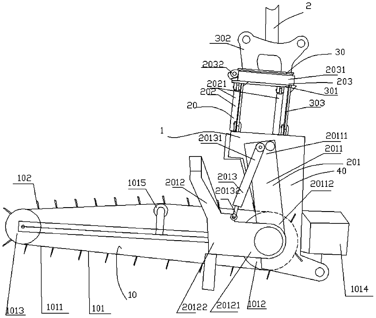
[0075] According to an embodiment of the present invention, the first end 20111 of the connecting arm 2011 is located on the upper side of the frame 40 , and the second end 20112 of the connecting arm 2011 is located on the lower side of the frame 40 .

[0076] When the stroke of the hydraulic cylinder 2013 is zero, the line connecting the central axes of the driven wheel 1013 and the driving wheel 1012 is substantially perpendicular to the line connecting the first end 20111 and the second end 20112 of the connecting arm. That is to say, the initial position of the line connecting the two wheel central axes of the transmission chain is approximately horizontal, as shown in figure 1 shown.

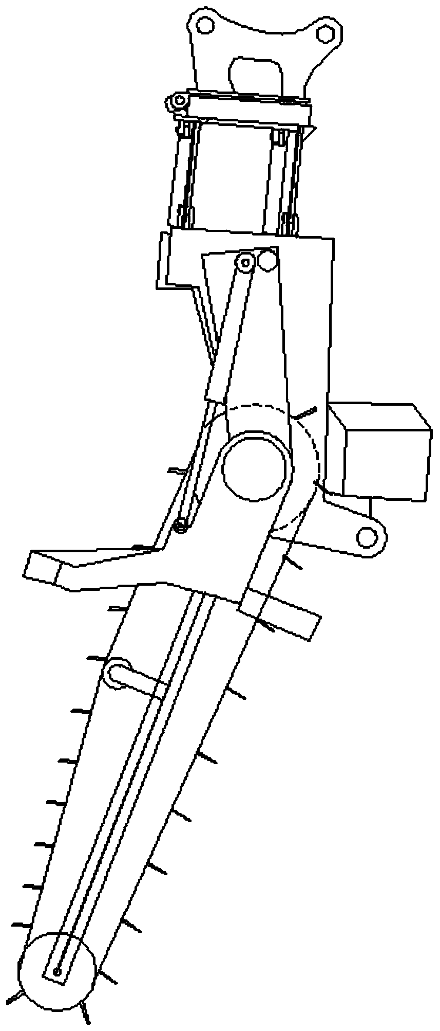
[0077] Such as figure 2 As shown, when the stroke of the hydraulic cylinder 2013 is maximum, the line connecting the central axis of the driven wheel 1013 and the driving wheel 1012 and the line connecting the first end 20111 and the second end 20112 of the connecting arm The included a...


PUM


Abstract

The invention relates to a soil cutting machine for soil in-situ moving. The soil cutting machine comprises a cutting part, an adjusting part and a force applying connecting part; the cutting part comprises a transmission chain module and cutting cutters, wherein the transmission chain module comprises a transmission chain and the transmission chain can be driven to perform annular motion, a groupof cutting cutters are arranged and the group of cutting cutters are arranged on the transmission chain at intervals, cutter handles of the cutting cutters are connected with the transmission chain,cutter heads of the cutting cutters extend out of the transmission chain, and connecting lines of the cutter heads and the cutter handles of the cutting cutters are approximately located on the annular surface of the transmission chain; the adjusting part is connected with the cutting part and is used for adjusting the direction of the cutting part; and the force applying connecting part, the cutting part and the adjusting part are integrally connected, so that the whole is pressed or lifted through the force applying connecting part. The machine is flexible and efficient, capable of rapidly adjusting the direction and carrying out multi-directional adjustment so as to perform cutting according to the required depth and size.

Description

technical field [0001] The invention relates to the technical field of in-situ relocation of soil, in particular to a soil cutting machine for in-situ relocation of soil. Background technique [0002] In the field of agricultural experiment technology, long-term positioning experiments can systematically explain the evolution of soil physics, chemistry, microorganisms and fertility due to fertilization and tillage, comprehensively evaluate fertilization effects and environmental changes, and provide scientific evidence for fertilization. Therefore, it has always been a subject of soil and fertilizer research. The most basic and effective method, and this method has been widely used by countries all over the world. Founded in 1843, the famous long-term positioning experiment of the Lausanne Experiment Station in the United Kingdom has been carried out continuously for 176 years, making important contributions to the development of agronomy, soil science, plant nutrition, ecol...

Claims


Application Information

Patent Timeline
IPC IPC(8): E02F3/08E02F3/12
CPCE02F3/08E02F3/088E02F3/142E02F3/145
Inventor 谷佳林邹国元刘善江杜连凤赵同科魏丹孙昊田野戴丽娜侯迎军梁丽娜秦金生田壮李吉进杨金凤刘建斌李顺江杜颖孙焱鑫陈益山徐森王悦李鹏薛文涛李新荣马良
Owner BEIJING ACADEMY OF AGRICULTURE & FORESTRY SCIENCES
Why Eureka
Try Eureka