Drill bit and drilling method with concentrated energy attack unloading bottom hole stress

A drill bit and energy-gathering technology, which is applied in the direction of drilling equipment and methods, drill bits, drilling equipment, etc., can solve the problems of complex drill bit and tool structure, limited application range, and low drilling efficiency, and is conducive to popularization and application. Unique, simple principle and structure effect

Active Publication Date: 2021-02-26
CHINA UNIV OF PETROLEUM (EAST CHINA)
View PDF5 Cites 0 Cited by
  • Summary
  • Abstract
  • Description
  • Claims
  • Application Information

AI Technical Summary

Problems solved by technology

The method of changing the bottom hole stress field by changing the shape of the bottom hole only needs to optimize the shape of the bit, change the shape of the bit teeth, or optimize the distribution of the bit teeth to achieve the effect of releasing the formation stress and increasing the drilling speed. However, until now, unloading Bottomhole stress drill bits and tools have complex structures, cumbersome installation and low drilling efficiency
Up to now, only the downhole drill string vibration reduction and booster technology has been used to assist rock breaking and speed increase technology with ultra-high pressure jets, and has been popularized and applied. However, this method needs to be boosted above the drill bit. It can achieve its goal, but its application scope is limited. The present invention provides a drill bit and drilling method with energy-gathering attack unloading bottomhole stress, which can not only achieve the goal of automatically releasing bottomhole stress, but also exert the bottomhole stress induced unloading to improve The effect of drilling speed can also improve the drilling speed of drilling and breaking rocks

Method used


Image

  • Drill bit and drilling method with concentrated energy attack unloading bottom hole stress
  • Drill bit and drilling method with concentrated energy attack unloading bottom hole stress
  • Drill bit and drilling method with concentrated energy attack unloading bottom hole stress

Examples


Embodiment Construction

[0024] In order to make the object, technical solution and advantages of the present invention more clear, the present invention will be further described in detail below in conjunction with the examples. It should be understood that the specific embodiments described here are only used to explain the present invention, and are not intended to limit the present invention, that is, the described embodiments are only some of the embodiments of the present invention, but not all of the embodiments.

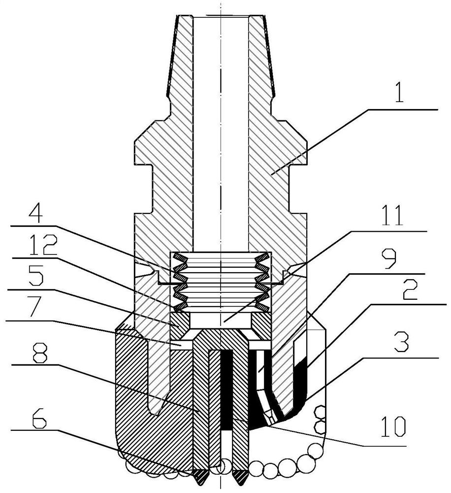
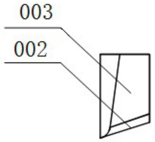
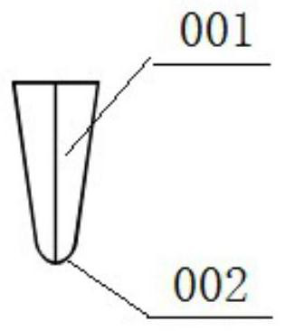
[0025] See attached Figure 1-4 , a drill bit utilizing energy-gathering attack to unload bottomhole stress, the drill bit includes a drill bit body, an energy-gathering spring 4 and an advantage attack assembly 5; the advantage attack assembly 5 is installed inside the drill bit body, and the advantage attack assembly 5 The energy-gathering attack tooth 6 at the bottom protrudes below the cutting teeth on the bottom surface of the drill bit body; the energy-gathering spring 4 is ins...


PUM


Abstract

The invention relates to a drill bit and a drilling method with energy-gathering attack unloading bottom hole stress. The drill bit includes a drill body, an energy-gathering spring and a dominant attack assembly. The energy-gathering attack teeth at the bottom of the assembly protrude from the cutting teeth on the bottom surface of the drill bit body, the energy-gathering spring is installed inside the drill bit body and above the dominant attack assembly, and the dominant attack assembly and the drill bit body can move axially relative to each other However, it cannot be rotated relative to each other, so that the energy-gathering attack teeth installed at the bottom of the power transmission shaft of the dominant attack assembly are ahead of the cutting teeth of the drill bit at the bottom of the crown of the drill bit body to break the bottom of the well and form a circular groove bottom to release the stress on the bottom of the well. The bit cutting teeth at the bottom of the crown of the bit body break the rock under pressure and torque. By releasing the stress first, and then breaking the rock at the bottom of the well, the whole process of breaking rock and increasing the drilling speed is realized.

Description

technical field [0001] The invention belongs to the field of drilling engineering, and in particular relates to a drill bit with energy-gathering attack unloading well bottom stress and a drilling method. Background technique [0002] During the drilling process, early release of the formation stress at the bottom of the well can effectively improve the rock-breaking efficiency of the drill bit, thereby increasing the drilling speed. So far, scholars at home and abroad have proposed two methods to release the bottomhole stress in advance. One is to change the bottomhole stress field by changing the shape of the bottomhole to release the formation stress. The other is a method of releasing formation stress based on hydraulic energy, represented by ultra-high pressure jet-assisted rock-breaking and speed-up technology. The method of changing the bottom hole stress field by changing the shape of the bottom hole only needs to optimize the shape of the bit, change the shape of t...

Claims


Application Information

Patent Timeline
Patent Type & Authority Patents(China)
IPC IPC(8): E21B10/36E21B10/38E21B7/00
CPCE21B7/00E21B10/36E21B10/38
Inventor 刘永旺管志川
Owner CHINA UNIV OF PETROLEUM (EAST CHINA)
Why Eureka
Try Eureka