A test tube automatic disinfection device for medical experiments

An automatic disinfection and experimental technology, applied in the medical field, can solve the problems of disinfection water discharge, cumbersome operation, low efficiency, etc., and achieve the effect of improving efficiency and simplifying the disinfection process

Inactive Publication Date: 2020-12-22
孟蔚 +1
View PDF8 Cites 0 Cited by
  • Summary
  • Abstract
  • Description
  • Claims
  • Application Information

AI Technical Summary

Problems solved by technology

Medical laboratories often need to use test tubes to hold pharmaceutical reagents. These test tubes need to hold different reagents, but there will be cross-reaction between reagents. Therefore, it is necessary to clean the used test tubes, and the cleaning process of test tubes is divided into In the process of cleaning, drying, disinfection, etc., the traditional disinfection device is to soak the test tube in disinfectant water, and then disinfect it manually by washing. The existing test tube disinfection device cannot automatically discharge the sterilized water in the test tube after disinfection. It needs to manually turn and dump the water in the test tube. The operation is cumbersome. In order to automatically drain the test tube after disinfection, we propose a medical experiment Automatic disinfection device for test tubes

Method used


Image

  • A test tube automatic disinfection device for medical experiments
  • A test tube automatic disinfection device for medical experiments
  • A test tube automatic disinfection device for medical experiments

Examples


Embodiment Construction

[0023] The following will clearly and completely describe the technical solutions in the embodiments of the present invention with reference to the accompanying drawings in the embodiments of the present invention. Obviously, the described embodiments are only some, not all, embodiments of the present invention. Based on the embodiments of the present invention, all other embodiments obtained by persons of ordinary skill in the art without making creative efforts belong to the protection scope of the present invention.

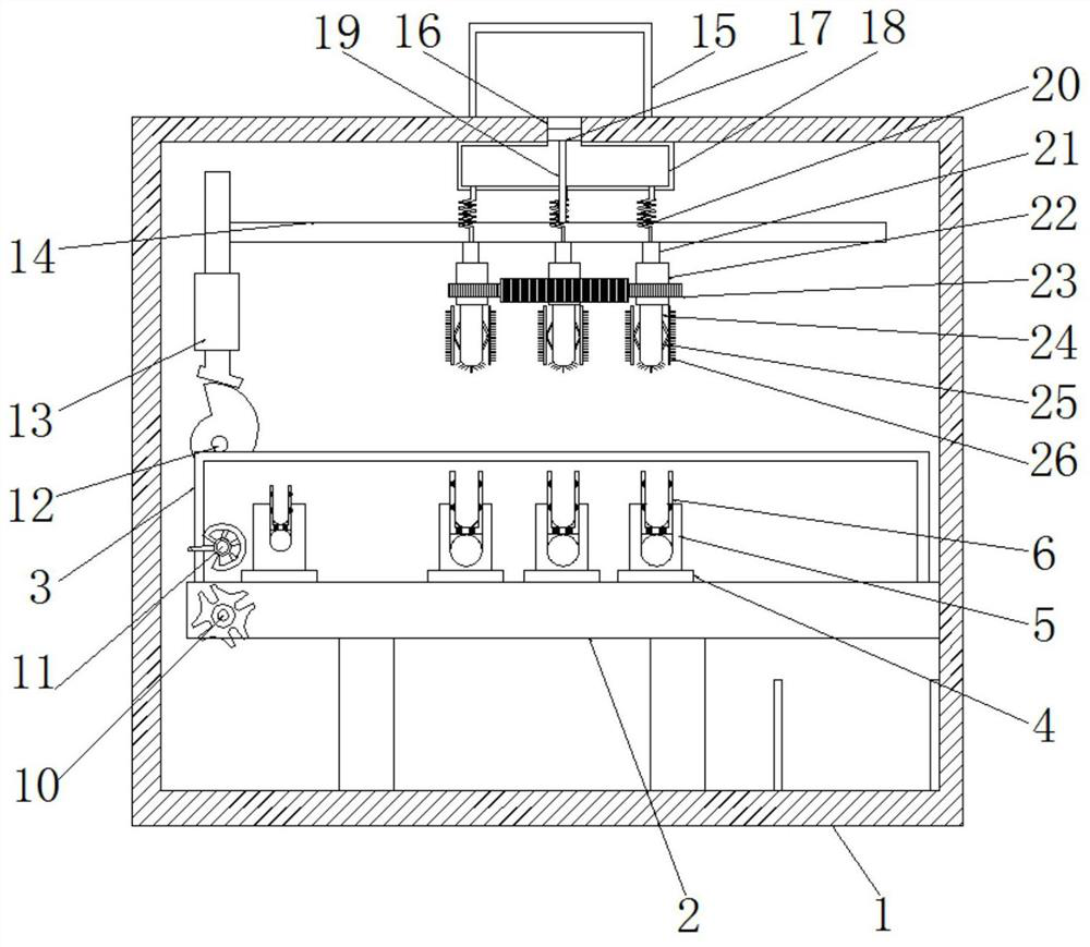
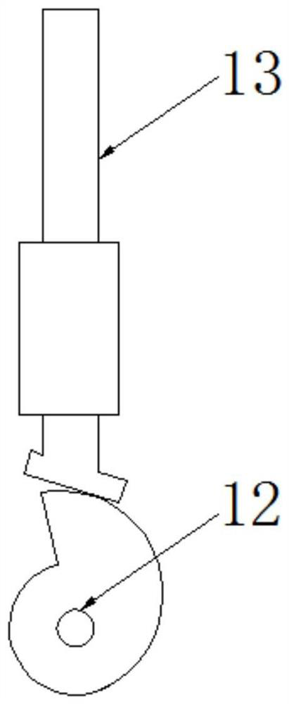
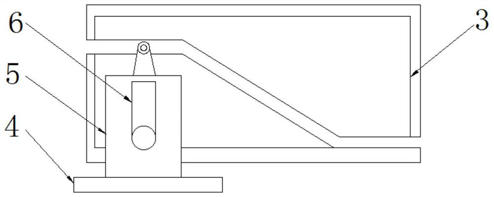
[0024] see Figure 1-8 , a test tube automatic disinfection device for medical experiments, comprising a box body 1, the inside of the box body 1 is movably connected with a conveyor belt 2, the back side of the conveyor belt 2 is fixedly connected with a baffle plate 3, and the front side of the baffle plate 3 is provided with a fixed groove, The fixed groove is divided into an upper chute, a chute and a lower chute, wherein the chute is located on the right ...


PUM


Abstract

The invention relates to the technical field of medical treatment and discloses an automatic test tube sterilization device for medical experiments. The automatic test tube sterilization device comprises a box body. A baffle is arranged on the back face of a conveyor belt. A moving plate is arranged on the top of the conveyor belt. A test tube frame is arranged on the front face of a fixed plate.Conical teeth are arranged on the outer side of a sleeve pipe. A water output pipe is arranged on the bottom of the sleeve pipe. A folded rod is arranged on the outer side of the water output pipe. Ahairbrush is arranged on the outer side of the folded rod. A water tank is arranged on the top of the box body. A storing box is arranged on the inner top wall of the box body. A connecting pipe is arranged on the bottom of the storing box. An opening is formed between the water tank and the storing box. A vertical rod is arranged on the bottom of a pushing plate. A pulling disc rotates to drive agroove wheel to rotate, a moving block moves to the slope of a fixing groove and moves downwards along the slope, the moving block rotates to drive the test tube frame to rotate through a rotating rod, the moving block moves to a lower sliding groove to rotate, the test tube frame is driven to rotate, the test tube frame rotates by 180 degrees, openings of test tubes are rotated to be downward, and water in the test tubes is poured out of the openings of the test tubes.

Description

technical field [0001] The invention relates to the field of medical technology, in particular to an automatic test tube disinfection device for medical experiments. Background technique [0002] A test tube is a reaction vessel used in a medical laboratory to hold a small amount of reagents. Medical laboratories often need to use test tubes to hold pharmaceutical reagents. These test tubes need to hold different reagents, but there will be cross-reaction between reagents. Therefore, it is necessary to clean the used test tubes, and the cleaning process of test tubes is divided into In the process of cleaning, drying, disinfection, etc., the traditional disinfection device is to soak the test tube in disinfectant water, and then disinfect it manually by washing. The existing test tube disinfection device cannot automatically discharge the sterilized water in the test tube after disinfection. It needs to manually turn and dump the water in the test tube. The operation is cum...

Claims


Application Information

Patent Timeline
Patent Type & Authority Patents(China)
IPC IPC(8): B08B9/36A61L2/18
CPCA61L2/18A61L2202/17A61L2202/23B08B9/0808B08B9/36
Inventor 孟蔚韩冰王涣
Owner 孟蔚
Why Eureka
Try Eureka