Positioning unit and monitoring device

a monitoring device and positioning unit technology, applied in the field of positioning units, can solve the problems of high risk of infection, high cost, and high cost of repeated sterilisation of other materials, and achieve the effect of convenient operation of connection

Active Publication Date: 2015-10-13
OCULUS OPTIKGERATE GMBH
View PDF34 Cites 3 Cited by
  • Summary
  • Abstract
  • Description
  • Claims
  • Application Information

AI Technical Summary

Benefits of technology

[0015]The positioning unit, according to the invention, for positioning an optical unit comprising at least one optical element in a beam path of a microscope between an objective lens of the microscope and in front of an eye to be monitored, comprises: (a) a connection device, by means of which the positioning unit can be coupled to the microscope, wherein the positioning unit comprises (b) a positioning device, by means of which the optical element is movable relative to the microscope in the longitudinal direction of the beam path, wherein the positioning device is formed of a first double rocker mechanism and a second double rocker mechanism, wherein the double rocker mechanisms are interconnected by means of a common coupling member. A movability of the optical element in the longitudinal direction of the beam path makes it possible to adjust the optical unit to the eye to be monitored, and / or to adjust the beam path of the microscope to an intermediate image located in the beam path without having to make these adjustments on the microscope. The double rocker mechanisms are preferably each formed of two rod-like rockers, which are each connected, in turn, at their ends to a pivot bearing. A movement of the first double rocker with the coupling member in a circular arc-shaped manner is thus enabled, wherein the second double rocker can likewise move in a circular arc-shaped manner in the same direction, in such a way that a linear movement in the longitudinal direction of the beam path is produced from both circular arc-shaped movements. Owing to this combination of two double rocker mechanisms, it is possible to dispense completely with a linear guide for moving the optical element. The double rocker mechanisms may be formed with single pivot points, or pivot bearings, which are substantially easier to sterilise or seal compared to linear guides. In addition, no specific maintenance or lubrication of the double rocker mechanisms is required, and there is no need to produce specific guides having correspondingly narrow tolerances. The rockers of the double rocker mechanisms, as well as the coupling member, can be produced in this instance from a plastics material, for example. It is also conceivable to form the pivot bearing, required for the connection, of plastics material. On the whole, a production cost for the positioning unit can thus be considerably reduced.
[0032]Alternatively, the positioning unit may form a holding means for holding the optical element. Consequently, the optical element may be held directly by the positioning unit without having to form a receiving device on the positioning unit. In particular, if the positioning unit is formed of plastics material, the holding means can be moulded integrally on the positioning device so that, in order to assemble the optical element, this only has to be inserted into the holding means.

Problems solved by technology

In particular, there is a risk of infection since the monitoring device is advanced relatively tightly against the eye in question during an operation.
Other materials, such as plastics materials, have not proven to be very durable for repeated sterilisation.
A weight of the monitoring device, which can be adapted, for example, to an adapter plate on the microscope screwed onto the microscope, is, therefore, relatively high and disruptive in the event of handling of the monitoring device during an operation.
The linear guides can also only be sealed or sterilised with difficulty.
During steam sterilisation, water or steam can only infiltrate the screw paths of the screw drive with difficulty, and, therefore, undesired water residues or germs may still remain in the screw paths after the steam sterilisation.
It is also disruptive that the lubricants used are removed, at least in part, during the steam sterilisation and contaminate the water used for sterilisation.
The sterilisation process itself is also to be considered problematic since it cannot be ruled out with absolute certainty that germs will still remain on the monitoring device and on the positioning unit after the steam sterilisation.
Furthermore, a monitoring device and a positioning unit are to be sterilised after each use, and, therefore, the monitoring device and positioning unit cannot be used directly after use in subsequent eye operations owing to the sterilisation times. As the case may be, it is necessary to obtain and have available a plurality of monitoring devices and positioning units so that operations can be carried out without any time restraint.
High overall costs for production, sterilisation, and maintenance of the monitoring device and positioning unit are thus sustained by a user, as well as costs incurred owing to increased capital investment.

Method used


Image

  • Positioning unit and monitoring device
  • Positioning unit and monitoring device
  • Positioning unit and monitoring device

Examples


Embodiment Construction

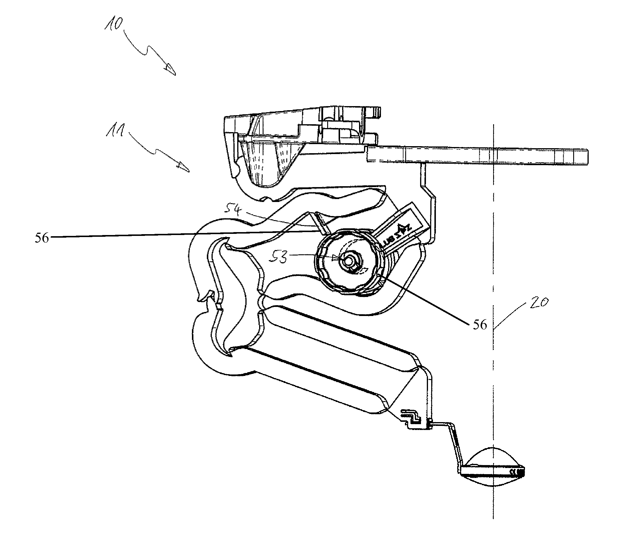
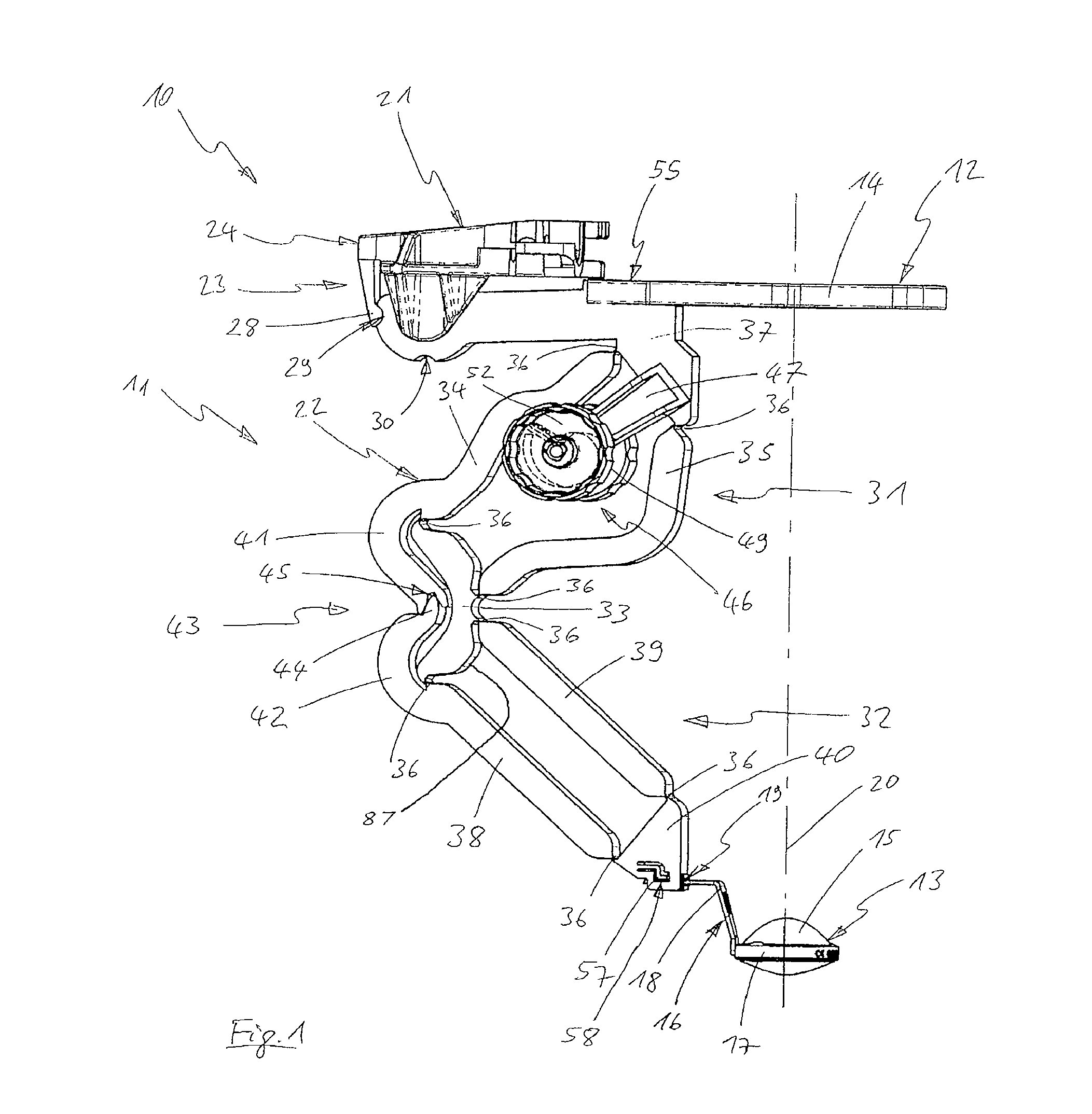
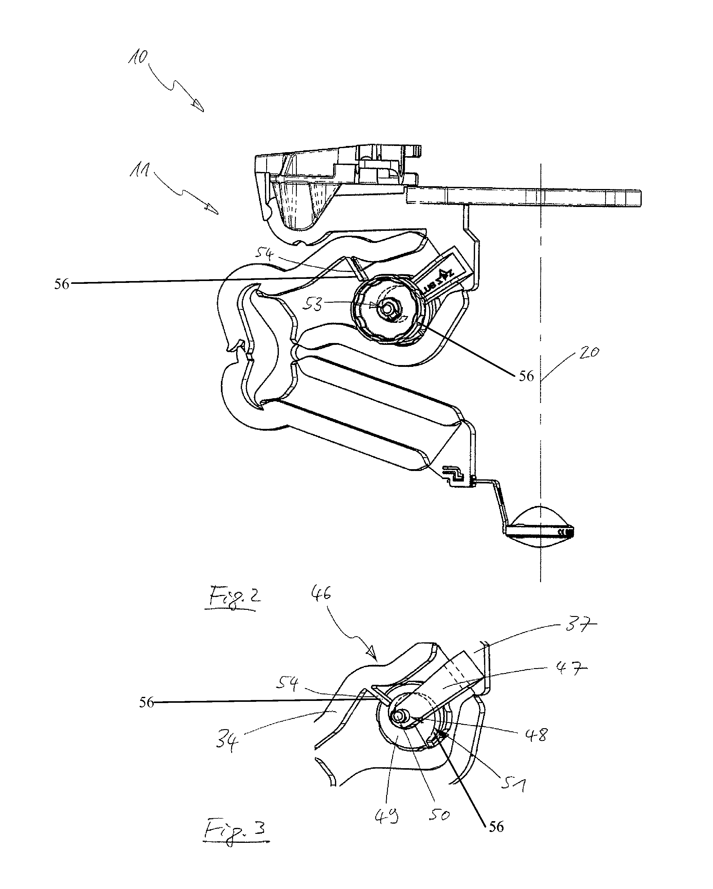
[0047]A monitoring device 10 comprising a positioning means 11 in various representations and positions can be derived by comparing FIGS. 1 to 5. The monitoring device 10 comprises optical units 12 and 13, wherein the optical unit 12 is only illustrated in part in this instance. Merely an annular holding means 14 of the optical unit 12, which annular holding means 14 is used to receive a reducing lens (not shown here) is illustrated in this instance. The optical unit 13 is formed by an ophthalmoscopy lens 15 and a holding means 16. The holding means 16 comprises a mount 17 for holding the ophthalmoscopy lens 15 and an angular holder 18 for connection to a receiving device 19 of the positioning means 11. The reducing lens (not shown in this instance) and the ophthalmoscopy lens 15 may be arranged in a beam path 20, illustrated suggestively in this instance, of a microscope (not shown in this instance than its beam path 20).

[0048]The positioning unit 11 comprises a connection device 2...


PUM


Abstract

A positioning unit (11) for positioning an optical unit (12, 13) comprising at least one optical element in a beam path (20) of a microscope between an objective lens of a microscope and in front of an eye to be monitored is provided, wherein the positioning unit comprises a connection device (21), by means of which the positioning unit can be coupled to the microscope, wherein the positioning unit comprises a positioning device (22), by means of which the optical element is movable relative to the microscope in the longitudinal direction of the beam path, wherein the positioning device is formed by a first double rocker mechanism (31) and a second double rocker mechanism (32), wherein the double rocker mechanisms are interconnected by means of a common coupling member (33). A monitoring device (10) is also provided that comprises the positioning unit (11).

Description

[0001]This application claims priority from German Patent Application No. DE 10 2011 002 941.9, filed Jan. 20, 2011, the entire disclosure of which is incorporated herein by reference.FIELD OF THE INVENTION[0002]The invention relates to a positioning unit for positioning an optical unit comprising at least one optical element in a beam path of a microscope between an objective lens of a microscope and in front of an eye to be monitored, wherein the positioning unit comprises a connection device by means of which the positioning unit can be coupled to the microscope, wherein the positioning unit comprises a positioning device, by means of which the optical element is movable relative to the microscope in the longitudinal direction of the beam path. The invention also relates to a monitoring device comprising such a positioning unit.BACKGROUND OF THE INVENTION[0003]Microscopes for carrying out eye operations are regularly used for operations in a front area of an eye. Should such inte...

Claims


Application Information

Patent Timeline
Patent Type & Authority Patents(United States)
IPC IPC(8): A61B3/10A61B19/00A61B3/00G02B7/00G02B7/02G02B21/00
CPCA61B19/26A61B3/0075G02B7/001G02B7/023G02B21/0012G02B7/021A61B2019/265A61B19/5223A61B2090/506A61B90/50A61B90/20
Inventor FEIERTAG, CARSTENPFEIFFER, GUENTERKIRCHHUEBEL, RAINER
Owner OCULUS OPTIKGERATE GMBH
Why Eureka
Try Eureka