A Pneumatic Servo Valve with Air Float Sliding Pair

An air-floating, sliding pair technology, applied in valve details, valve devices, multi-way valves, etc., can solve the problems of short life and low sensitivity of valve core action, reduce friction damping, improve service life and reliability, The effect of reducing the phenomenon of wear and tear

Active Publication Date: 2020-11-17
HUAZHONG UNIV OF SCI & TECH
View PDF2 Cites 0 Cited by
  • Summary
  • Abstract
  • Description
  • Claims
  • Application Information

AI Technical Summary

Problems solved by technology

[0005] Aiming at the above defects or improvement needs of the prior art, the present invention provides a pneumatic servo valve with an air-floating sliding pair, which sets air-floating valve shoulders at both ends of the valve core so that After entering the gas, the valve core is floated in the valve sleeve through the static pressure support cavity formed by the air-floating valve shoulder and the valve sleeve, avoiding frictional contact with the valve sleeve, and solving the problem between the sliding pair of the existing pneumatic servo valve valve core and valve sleeve. The friction and wear of the spool lead to low sensitivity and short life of the spool, and at the same time improve the control accuracy and dynamic response of the pneumatic servo valve

Method used


Image

  • A Pneumatic Servo Valve with Air Float Sliding Pair
  • A Pneumatic Servo Valve with Air Float Sliding Pair
  • A Pneumatic Servo Valve with Air Float Sliding Pair

Examples


Embodiment Construction

[0026] In order to make the object, technical solution and advantages of the present invention clearer, the present invention will be further described in detail below in conjunction with the accompanying drawings and embodiments. It should be understood that the specific embodiments described here are only used to explain the present invention, not to limit the present invention. In addition, the technical features involved in the various embodiments of the present invention described below can be combined with each other as long as they do not constitute a conflict with each other.

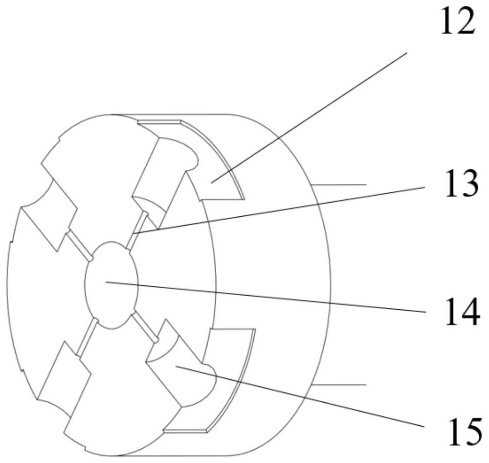
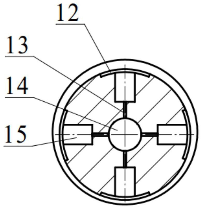
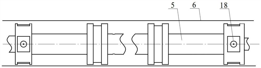
[0027] Such as figure 1 and 2 As shown, a pneumatic servo valve with an air-floating sliding pair is provided with an air-floating sliding pair, wherein: the air-floating sliding pair includes a valve core 5 and a valve sleeve 6, and the The valve core 5 is arranged in the valve sleeve 6, and the two ends of the valve core 5 are provided with an air-floating valve shoulder 18, and the air-floa...


PUM


Abstract

The invention belongs to the field of pneumatic valves, and discloses a pneumatic servo valve with an air floating type sliding pair. The air floating type sliding pair is arranged in the pneumatic servo valve and comprises a valve element and a valve sleeve. The valve element is arranged in the valve sleeve. Air floating type valve shoulders are arranged at the two ends of the valve element and are in a cylindrical shape. Blind holes communicating with a center hole of the valve element are formed in the middles of the air floating type valve shoulders. A plurality of grooves communicating with the blind holes are formed in the air floating type valve shoulders in the circumferential direction. A static pressure bearing cavity is formed by each groove and the inner wall of the valve sleeve. When gas is introduced into the center hole of the valve element, the gas enters the static pressure bearing cavities, the pressure of the gas in the static pressure bearing cavities acts on the valve element, the valve element is suspended in the valve sleeve, and accordingly friction between the valve element and the inner wall of the valve sleeve during transverse movement is reduced. By means of the pneumatic servo valve, the problems that due to friction abrasion between a valve element sliding pair and a valve sleeve sliding pair of an existing pneumatic servo valve, the action sensitivity of a valve element is low, and the service life is short are solved, and meanwhile the control precision and dynamic response of the pneumatic servo valve are improved.

Description

technical field [0001] The invention belongs to the field of pneumatic valves, and more specifically relates to a pneumatic servo valve with an air-floating sliding pair. Background technique [0002] Pneumatic technology is widely used in various fields of modern industry because the working medium is compressed air, which has the advantages of low cost, clean energy and no pollution, and easy operation. The performance of the pneumatic servo system depends largely on the control accuracy, dynamic and static performance of the pneumatic servo valve used. Therefore, improving the parameters and indicators of the pneumatic servo valve is very important to improve the performance of the pneumatic system. [0003] In the past ten years, there have been few studies on pneumatic servo valves at home and abroad, especially no scholars have proposed pneumatic servo valves with air-floating sliding pairs. Pneumatic servo valves are high-response, high-precision precision components ...

Claims


Application Information

Patent Timeline
Patent Type & Authority Patents(China)
IPC IPC(8): F16K11/07F16K27/04F16K37/00
CPCF16K11/0708F16K27/041F16K37/0083
Inventor 高隆隆李宝仁张迪嘉傅晓云杜经民杨钢
Owner HUAZHONG UNIV OF SCI & TECH
Why Eureka
Try Eureka