Robot mechanical arm

A technology of robots and mechanical arms, applied in the field of industrial robots, can solve the problems of inability to complete welding tasks, affecting welding quality, affecting welding efficiency, etc., to improve welding efficiency and quality, improve welding scope, and improve welding efficiency and quality. Effect

Inactive Publication Date: 2020-05-15
盐城市沿海新能源汽车科技有限公司
View PDF7 Cites 8 Cited by
  • Summary
  • Abstract
  • Description
  • Claims
  • Application Information

AI Technical Summary

Problems solved by technology

[0003] The welding robot has 6 degrees of freedom. The fixed base 1 can control the mechanical arm to rotate 360 ​​degrees in situ. At the same time, the movable shoulder 3 and the movable elbow 4 can respectively rotate 180 degrees in the same plane, providing long-distance support and positioning for the welding torch. But the greater the angle that the movable shoulder 3 and the movable elbow 4 extend, that is, the farther the horizontal distance between the welding torch and the fixed base 1 is, the lower the joint between the movable shoulder 3 and the movable elbow 4 will be. The height of the parts is too high, the movable shoulder 3 and the movable elbow 4 are not enough to transfer the welding torch to the bottom of the back of the large part for welding, and the welding task cannot be completed. At the same time, when the welding robot performs welding, at least two mechanical The straight-line welding can only be completed by the cooperation of the arms, which requires fine calculation and complex program control, which greatly affects the welding efficiency, and during the operation of the robot arm, if one of them deviates slightly, the welding path will deviate. Affect welding quality

Method used


Image

  • Robot mechanical arm
  • Robot mechanical arm
  • Robot mechanical arm

Examples


Embodiment Construction

[0023] The following will clearly and completely describe the technical solutions in the embodiments of the present invention with reference to the accompanying drawings in the embodiments of the present invention. Obviously, the described embodiments are only some, not all, embodiments of the present invention. Based on the embodiments of the present invention, all other embodiments obtained by persons of ordinary skill in the art without making creative efforts belong to the protection scope of the present invention.

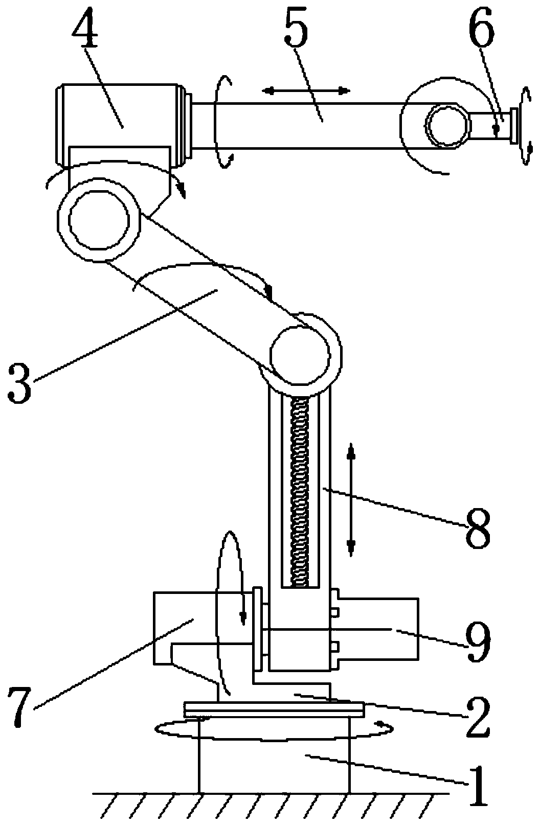
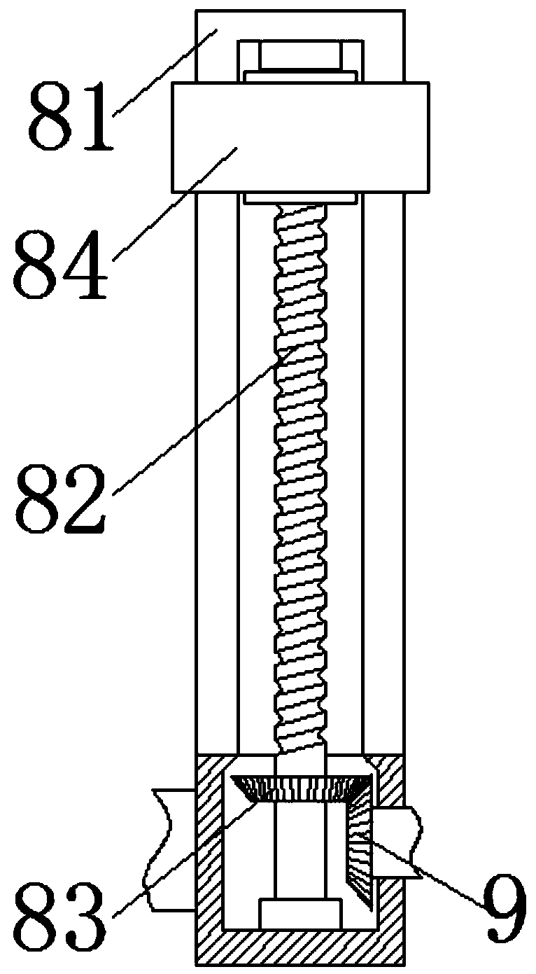
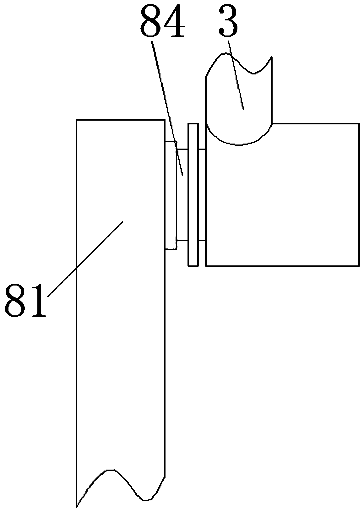
[0024] see Figure 1-6 , a robot mechanical arm, including a fixed base 1, a servo motor and a precision harmonic reducer, the top of the fixed base 1 is movably connected with a rotating base 2, and the upper left part of the rotating base 2 is fixedly equipped with a fixed servo motor 7, and the fixed servo The extension shaft at the right end of the motor 7 is fixedly equipped with connecting arm 8, the bottom of connecting arm 8 right side is fixedly insta...


PUM


Abstract

The invention relates to the technical field of industrial robots, and discloses a robot mechanical arm. The robot mechanical arm comprises a fixed base, a servo motor and a precise harmonic reducer.The mechanical arm can rotate in the YZ plane, a movable shoulder and a movable elbow are conveyed to the side edge of a large part, then the position and posture of a welding gun are adjusted throughthe movable shoulder, the movable elbow, a sliding rod and an executive part connecting rod so as to reach the position needing welding, the freedom degree of the welding robot is increased, the welding range is widened, and the limitation of the welding robot by the size of a welding part is reduced; meanwhile, due to the arrangement of the sliding rod, when the welding gun carries out linear welding on the welded part, direct control can be carried out through linear advancing, cooperative use of two or more mechanical arms is reduced, the complex degree of the moving track of the mechanical arms is reduced, and the calculated amount and workload of workers are reduced; and the complexity of program control is reduced, the operation speed of the mechanical arm is increased, and the welding efficiency and quality are improved.

Description

technical field [0001] The invention relates to the technical field of industrial robots, in particular to a robot arm. Background technique [0002] Industrial robots have had a significant impact on people's daily life and high-tech industries, and welding robots are one of the industrial robots. Welding robots are a highly automated welding equipment. The use of robots to replace manual welding operations is the development of the welding manufacturing industry. The trend is an important means to improve welding quality, reduce costs, and improve the working environment. At present, the body of a welding robot is generally a 6-axis articulated manipulator driven by a servo motor and a precision harmonic reducer. Figure 7 As shown, it consists of a driver, a transmission mechanism, a robotic arm, joints, and internal sensors, etc., which can accurately ensure the position, attitude, and trajectory of the welding torch at the end of the robotic arm, but there are some short...

Claims


Application Information

Patent Timeline
Patent Type & Authority Applications(China)
IPC IPC(8): B23K37/02B25J9/04
CPCB23K37/0252B25J9/04Y02P70/10
Inventor 刘玮厉冯鹏万益东经成林鑫焱
Owner 盐城市沿海新能源汽车科技有限公司
Why Eureka
Try Eureka