Through-shaft axial piston pump capable of realizing energy recovery

An axial piston pump and energy recovery technology, which is applied to the components, pumps, multi-cylinder pumps, etc. of the pumping device for elastic fluid, which can solve the problem of affecting the service life and utilization rate of seawater desalination equipment, and does not have the ability to recycle waste seawater. Pressure energy, lack of energy recovery function, etc., to achieve the effect of simple structure, guaranteed strength, and reduced structure size

Inactive Publication Date: 2020-06-05
YANSHAN UNIV +1
View PDF7 Cites 1 Cited by
  • Summary
  • Abstract
  • Description
  • Claims
  • Application Information

AI Technical Summary

Problems solved by technology

In my country's seawater desalination projects, a large amount of waste concentrated seawater with a certain pressure energy will be produced. If the factory fails to fully utilize the waste concentrated seawater, it will cause a waste of energy in the waste fluid
It not only increases the production cost of fresh water and reduces production efficiency, but also affects the service life and utilization rate of seawater desalination equipment
[0003] The main function of the traditional thru-shaft axial plunger pump is to distribute the flow through the valve plate, and the plunger moves back and forth in the cylinder to realize the suction of low-pressure fluid and the discharge of high-pressure fluid, and it does not have the function of recovering the pressure energy of waste seawater.
Ordinary seawater desalination high-pressure pumps also do not have the function of energy recovery, and the efficiency is lower

Method used


Image

  • Through-shaft axial piston pump capable of realizing energy recovery
  • Through-shaft axial piston pump capable of realizing energy recovery

Examples


Embodiment Construction

[0024] Below in conjunction with embodiment the present invention is described in further detail:

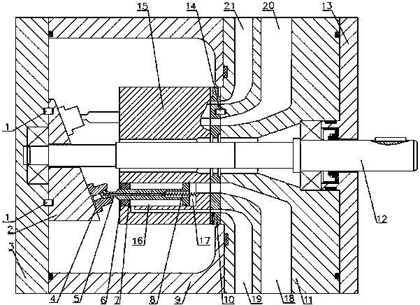
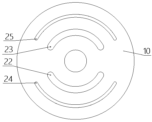
[0025] Such as figure 1 and figure 2 As shown, a thru-shaft axial piston pump for realizing energy recovery includes a pump body, a transmission shaft 12, a cylinder body 15, a swash plate 2, a piston 5, and a piston reset device. The transmission shaft 12 of the cylinder body 15 is coaxially fixedly connected, and the cylinder body 15 is arranged inside the cavity of the pump body. The swash plate 2 is fixedly connected inside the cavity of the pump body, and the swash plate 2 forms a certain angle with the axis of the cylinder body 15 . The cylinder body 15 is provided with axial holes uniformly distributed along the circumference, and a piston 5 is arranged inside the axial hole. One end of the piston 5 passes through the bottom of the cylinder body 15 and abuts against the swash plate 2, and the swash plate 2 and the distribution plate 10 are fixed. Do not move. The bal...


PUM


Abstract

The invention discloses a through-shaft axial piston pump capable of realizing energy recovery, and relates to the technical field of fluid machinery. The through-shaft axial piston pump comprises a pump body, a transmission shaft, a cylinder body, a swash plate, wherein an axial hole is formed in the cylinder body, and a piston is arranged inside the axial hole; the through-shaft axial piston pump further comprises a piston resetting device; an inner cavity of the cylinder body comprises a rodless cavity located on the side, away from the swash plate, of the right side of the piston as well as a rod cavity located on the left side of the rodless cavity and internally provided with a piston rod, wherein the rod cavity and the rodless cavity communicate with the outside of the cylinder bodythrough channels; and the pump body is further provided with a first fluid discharge channel, a first fluid indraft flow channel, a second fluid indraft channel and a second fluid discharge flow channel. According to the through-shaft axial piston pump capable of realizing energy recovery, input of external force is effectively reduced, recycling of waste energy is achieved, the structure is simple, manufacturing is convenient, lubricating effects of the piston are improved, friction is reduced, good economic benefits are brought, and adaptability is high.

Description

technical field [0001] The invention relates to the technical field of fluid machinery, in particular to a thru-shaft axial piston pump for realizing energy recovery. Background technique [0002] my country is rich in water resources, but the per capita share is relatively small. At the same time, due to the large population in our country, the demand for fresh water is very large. In my country's seawater desalination projects, a large amount of waste concentrated seawater with a certain pressure energy will be produced. If the factory fails to fully utilize the waste concentrated seawater, it will cause a waste of energy in the waste fluid. It not only increases the production cost of fresh water and reduces production efficiency, but also affects the service life and utilization rate of seawater desalination equipment. [0003] The main function of the traditional through-shaft axial plunger pump is to distribute flow through the valve plate, and the plunger moves back ...

Claims


Application Information

Patent Timeline
Patent Type & Authority Applications(China)
IPC IPC(8): F04B1/2014F04B1/2042F04B1/22F04B1/30F04B53/14
CPCF04B1/2014F04B1/2042F04B1/22F04B1/30F04B53/144
Inventor 张齐生李文雷王国刚于琳于大飞赵静一
Owner YANSHAN UNIV
Why Eureka
Try Eureka