
A batch installation device for server motherboard memory sticks
A technology for installing devices and memory sticks, which is applied in the field of mass installation of memory sticks on server motherboards, can solve problems such as low installation efficiency and high labor intensity, and achieve the effects of easy lifting, reduced scrap rate, and reduced labor intensity
- Summary
- Abstract
- Description
- Claims
- Application Information
AI Technical Summary
Problems solved by technology
Method used
Image

Examples
Embodiment 1
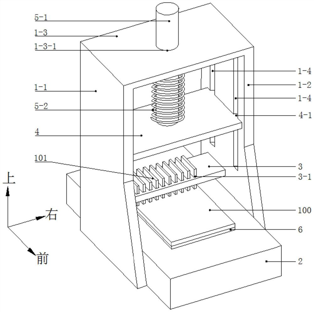
[0047] A device for installing memory sticks in batches on a server motherboard, such as figure 1 As shown, it includes a bracket, a base 2, a memory module loading plate 3, and a mounting plate 4.
[0048] Such as figure 1 As shown, the bracket includes a first support plate 1-1, a second support plate 1-2, and a top plate 1-3. The first support plate 1-1 and the second support plate 1-2 are arranged side by side, and the upper ends of the first support plate 1-1 and the second support plate 1-2 are welded and fixed to the top plate 1-3.
[0049] Such as figure 1 As shown, the base 2 is arranged between the first support plate 1-1 and the second support plate 1-2, and the lower end of the first support plate 1-1 and the lower end of the second support plate 1-2 are welded and fixed to the base 2 .
[0050] Such as figure 1 As shown, the memory stick loading plate 3 is arranged between the top plate 1-3 and the base 2, the memory stick loading plate 3 is provided with a p...
Embodiment 2
[0068] During the mass installation process of the memory sticks 101 in the first embodiment, the server mainboard 100 may be skewed or slipped sometimes due to an operator's mistaken touch or the shaking of the bracket, so that the memory sticks 101 cannot be aligned with the memory slots of the server mainboard 100 .
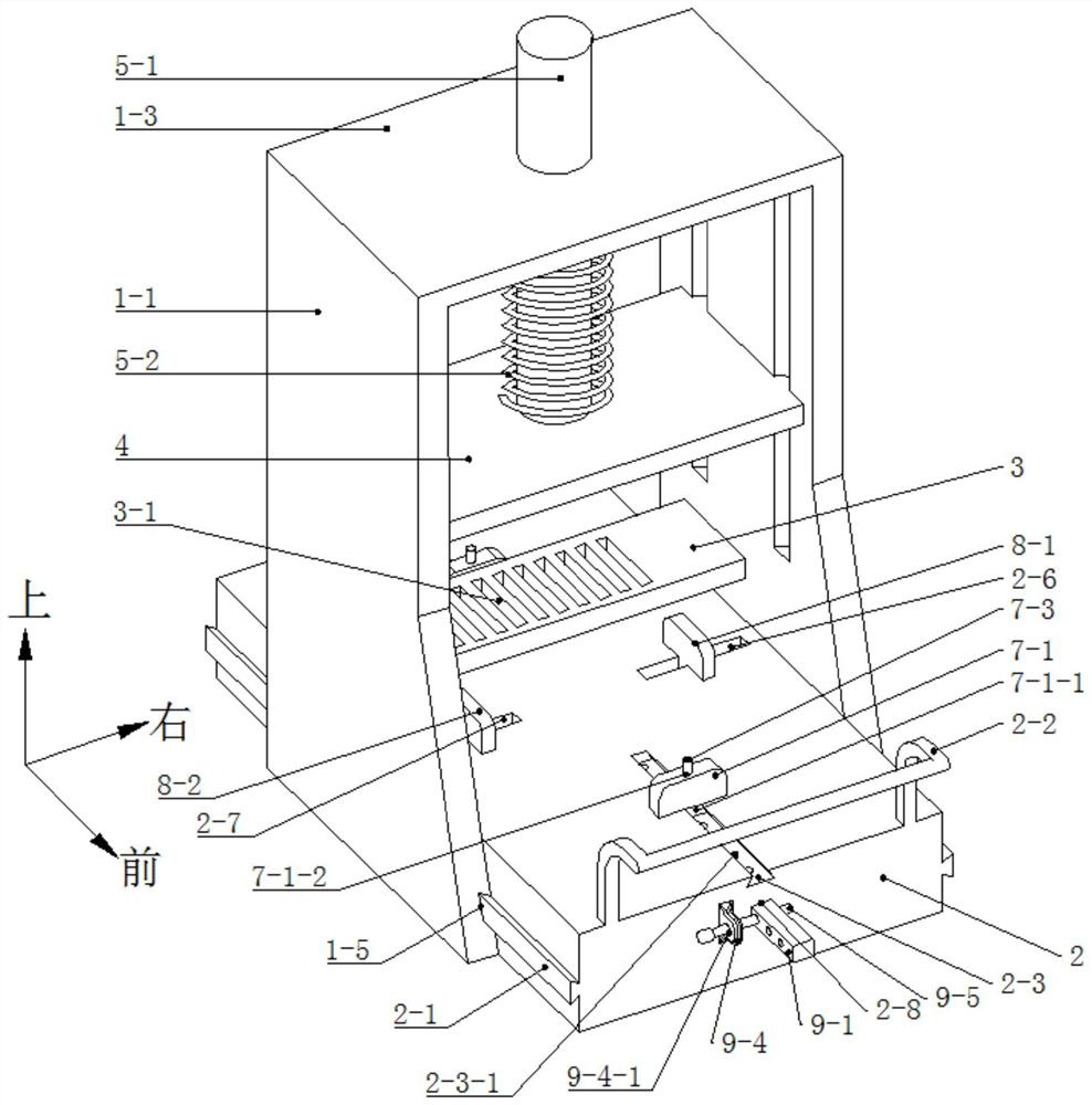
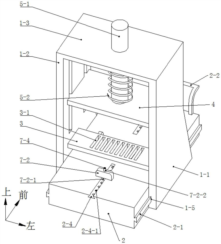
[0069] For this, if figure 2 As shown, the second embodiment is based on the first embodiment, and a clamping mechanism for clamping the server mainboard 100 is provided on the upper surface of the base 2 . The clamping mechanism includes a first clamping assembly and a second clamping assembly. The first clamping assembly clamps the server main board 100 from the front and rear directions, and the second clamping assembly clamps the server main board 100 from the left and right directions.
[0070] Such as figure 2 and image 3 As shown, the first clamping assembly includes a first clamping plate 7-1 and a second clamping plate 7-2 arranged side by side,...
Embodiment 3
[0096] The third embodiment is the same as the second embodiment, except that it is in a batch installation device for memory sticks on the main board of the server in the third embodiment. Such as Figure 6 As shown, the lifting mechanism includes a rotating rod 10-1, a cam 10-2, and a reset elastic member 10-3. Both the first support plate 1-1 and the second support plate 1-2 are rotationally connected with the rotating rod 10-1, the cam 10-2 is welded and fixed with the rotating rod 10-1, and the cam 10-2 cooperates with the mounting plate 4 to restore elasticity Part 10-3 is located between the top plate 1-3 and the mounting plate 4, the reset elastic part 10-3 adopts a spring, the upper end of the spring is welded with the top plate 1-3, and the lower end of the spring is welded with the mounting plate 4.
[0097] Such as Figure 6As shown, specifically, the structure that realizes that both the first support plate 1-1 and the second support plate 1-2 are rotationally c...
PUM
 Abstract
Description
Claims
Application Information