centrifugal clutch

A centrifugal clutch and clutch technology, applied in clutches, automatic clutches, transmissions, etc., can solve the problems of complex structure, increased manufacturing burden, and reduced fuel consumption rate.

Active Publication Date: 2022-03-29
FCC KK
View PDF22 Cites 0 Cited by
  • Summary
  • Abstract
  • Description
  • Claims
  • Application Information

AI Technical Summary

Problems solved by technology

[0007] However, in the centrifugal clutch described in the above-mentioned Patent Document 1, the clutch weight gradually comes into frictional contact with the clutch cover as the engine speed increases, so there is a problem that the time from when the engine speed starts to increase until the clutch is in the connected state is relatively short. Longer and lower fuel consumption, and smaller clutch capacity
On the other hand, in the centrifugal clutch described in the above-mentioned Patent Document 2, the drive plate rotated by the rotation of the engine is composed of two pieces, such as the first drive plate and the second drive plate, so the structure is complicated due to the increase in the number of parts. problem of increased manufacturing burden

Method used


Image

  • centrifugal clutch
  • centrifugal clutch
  • centrifugal clutch

Examples


Embodiment Construction

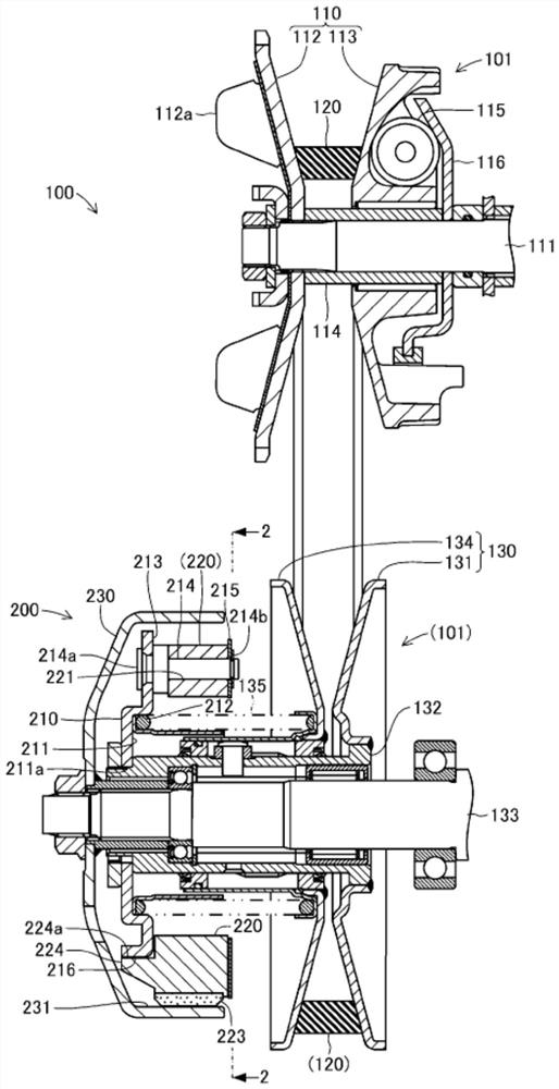
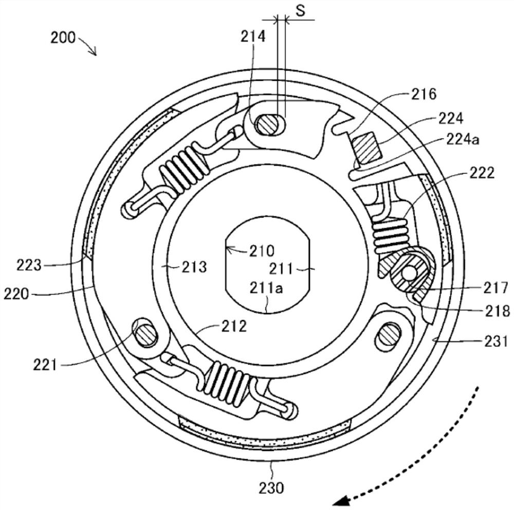
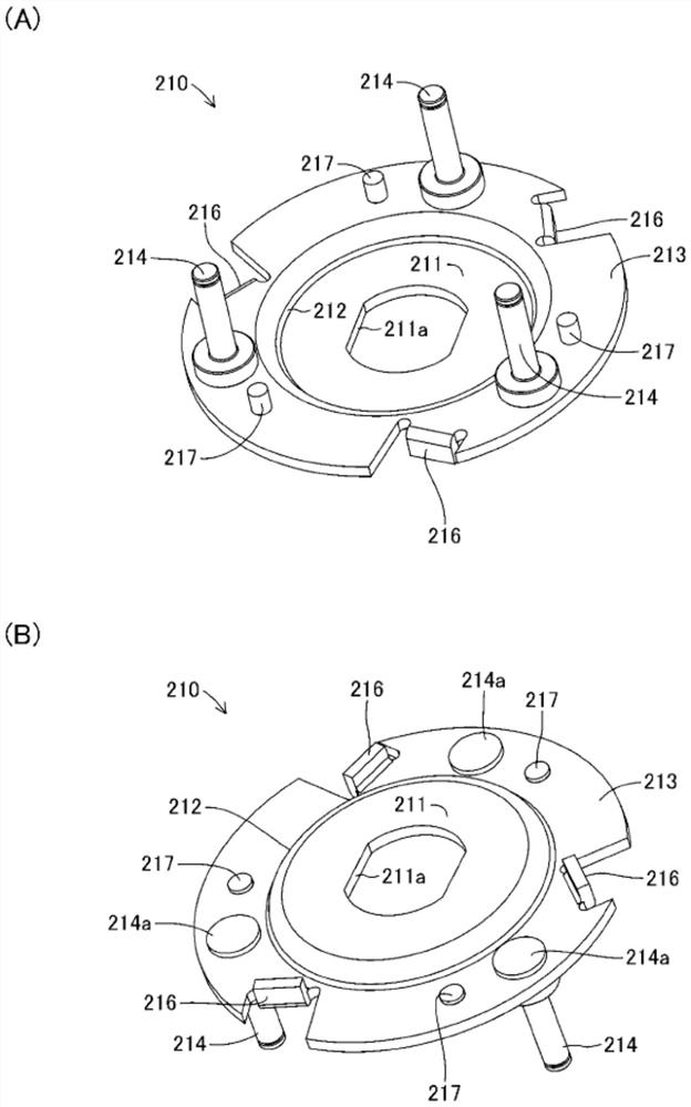
[0058] One embodiment of the centrifugal clutch according to the present invention will be described below with reference to the drawings. figure 1 It is a top sectional view schematically showing the configuration of the power transmission mechanism 100 including the centrifugal clutch 200 of the present invention. again, figure 2 By figure 1 A side view of the centrifugal clutch 200 is shown on line 2-2. The power transmission mechanism 100 including the centrifugal clutch 200 is a mechanical device that is installed between the engine and the rear wheels as drive wheels mainly in a motorcycle such as a scooter, and automatically changes the speed reduction ratio with respect to the number of revolutions of the engine. Transmit or block the rotational driving force on the rear wheel.

[0059] (Configuration of Centrifugal Clutch 200)

[0060] This power transmission mechanism 100 mainly includes a transmission 101 and a centrifugal clutch 200 . The transmission 101 is ...


PUM


Abstract

The present invention provides a centrifugal clutch capable of increasing the clutch capacity with a simple configuration. The centrifugal clutch 200 includes a drive plate 210 that is directly rotationally driven by engine driving force. The drive plate 210 includes a swing support pin 214 and a guide portion 216 , respectively. The swing support pin 214 is fitted in a pin sliding hole 221 formed in the clutch weight 220 to swingably support the clutch weight 220 . The guide portion 216 is formed in the shape of a notch or a hole and extends toward the rear and outward in the rotational driving direction of the drive plate 210 and extends obliquely, and contacts the protrusion 224 of the clutch weight 220 . The pin slide hole 221 is formed in the shape of an elongated hole allowing the displacement of the clutch weight 220 to the rear side in the rotational driving direction of the driving plate 210 . The protruding body 224 is formed by protruding from the clutch weight 220 .

Description

technical field [0001] The present invention relates to a centrifugal clutch, which blocks the transmission of the rotational driving force to the driven side before the engine reaches a predetermined number of rotations, and transmits the rotational driving force to the driven side when the engine reaches the predetermined number of rotations. Background technique [0002] Conventionally, in motorcycles, lawnmowers, etc., a centrifugal clutch is used that transmits rotational driving force to the driven side when the engine reaches a predetermined number of revolutions. For example, the following patent document 1 discloses a centrifugal clutch in which the clutch counterweight disposed on one drive plate gradually displaces toward the clutch housing side as the engine speed increases, and the clutch shoe disposed on the clutch counterweight shifts toward the clutch housing. Frictional contact with clutch weight. In addition, the following patent document 2 discloses a cen...

Claims


Application Information

Patent Timeline
Patent Type & Authority Patents(China)
IPC IPC(8): F16D43/18
CPCF16D43/18F16D2043/145F16H9/18F16H55/56
Inventor 青野薰市位诚之横道友太木根悠太片冈真
Owner FCC KK
Why Eureka
Try Eureka