Power transmission mechanism for wood processing machine

A technology of power transmission mechanism and processing machinery, which is applied in the direction of mechanical equipment, transmission boxes, transmission parts, etc., can solve problems such as time-consuming and laborious, cumbersome process, and influence on the performance of power transmission mechanism, so as to achieve improved stability and simple overall structure , low cost effect

Inactive Publication Date: 2017-02-01
邹昌金
View PDF0 Cites 0 Cited by
  • Summary
  • Abstract
  • Description
  • Claims
  • Application Information

AI Technical Summary

Problems solved by technology

In order to ensure the sliding performance between the bearing seat and the power transmission teeth, it is necessary to add oil to the bearing seat. The existing power transmission mechanism is limited by its own structure. The process of adding oil to the bearing seat is cumbersome, time-consuming and laborious. If no oil is added for a long time, it will seriously affect the performance of the power transmission mechanism

Method used


Image

  • Power transmission mechanism for wood processing machine

Examples


Embodiment

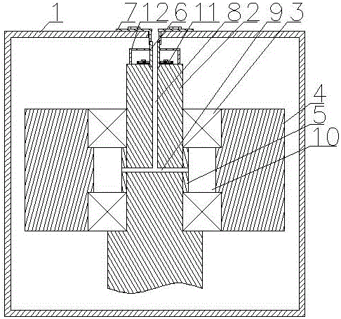
[0014] Such as figure 1 As shown, the power transmission mechanism for wood processing machinery includes a housing 1, a drive shaft 2, a bearing seat 3, a power transmission tooth 4, an oil guide assembly and a driven shaft limit assembly 12, wherein the drive shaft 2, the bearing The seat 3 and the power transmission gear 4 are both arranged in the housing 1, the bearing seat 3 is paired and arranged between the power transmission tooth 4 and the drive shaft 2, the inner ring of the bearing seat 3 cooperates with the drive shaft 2, and the outer ring of the bearing seat 3 matches the power transmission shaft 2. Transmission tooth 4 cooperates. An annular oil storage chamber 10 is formed between the drive shaft 2, the bearing housing 3 and the power transmission gear 4 in this embodiment, and the drive shaft 2 is formed with a first oil tank that is vertically arranged and whose upper opening is located at the top of the drive shaft 2. The liquid flow hole 8 and the second o...


PUM


Abstract

The invention discloses a power transmission mechanism for a wood processing machine. The power transmission mechanism comprises a shell, a driving shaft, bearing pedestals, a power transmission gear, an oil flow guiding assembly and a driven shaft limiting assembly. The driving shaft, the bearing pedestals and the power transmission gear define an oil storage cavity. A first oil circulating hole and a second oil circulating hole are formed in the driving shaft. The oil flow guiding assembly comprises a tubular driven shaft and a driven shaft fixing piece. The driven shaft fixing piece comprises a positioning tube and an annular positioning table. The positioning tube penetrates through the top of the shell, and the annular positioning table is fixed to the shell. The upper end and the lower end of the tubular driven shaft make contact with the bottom of the positioning tube and the top of the driving shaft correspondingly. The bottom of the side wall of the positioning tube is recessed inwards to form a limiting groove. The top of the side wall of the tubular driven shaft protrudes upwards to form a joint tube, and the joint tube is embedded into the limiting groove. The driven shaft limiting assembly comprises a supporting rod and a limiting ring. The tubular driven shaft penetrates through an inner ring body of the limiting ring. When the power transmission mechanism is applied, oil can be added to the bearing pedestals conveniently, and thus reliability and stability of the power transmission mechanism during application can be guaranteed.

Description

technical field [0001] The invention relates to furniture processing technology, in particular to a power transmission mechanism for wood processing machinery. Background technique [0002] In recent years, wood processing machinery has been greatly improved in terms of equipment structure and automatic program control. As an important part of wood processing machinery, the power transmission mechanism includes a drive shaft, a bearing seat and a power transmission tooth. Among them, the bearing seat is paired between the power transmission tooth and the drive shaft, and the inner ring of the bearing seat cooperates with the drive shaft. The outer ring of the seat cooperates with the power transmission teeth. When the power transmission mechanism in wood processing machinery is used, the power of the motor is transmitted through the drive shaft, the bearing seat and the power transmission teeth. In order to ensure the sliding performance between the bearing seat and the pow...

Claims


Application Information

Patent Timeline
Patent Type & Authority Applications(China)
IPC IPC(8): F16H57/04F16H57/023F16H57/03
CPCF16H57/0427F16H57/023F16H57/03F16H57/043F16H57/0452
Inventor 邹昌金
Owner 邹昌金
Why Eureka
Try Eureka