Full-automatic adjustable and portable optical cable stripping device

An adjustable and portable technology, applied in the direction of light guide, optics, instruments, etc., can solve the problems of personal safety hazards, labor, and time-consuming process of optical cable stripping, so as not to waste material resources, meet the needs of stripping, and avoid direct contact Effect

Pending Publication Date: 2020-07-24
国网江苏省电力有限公司淮安供电分公司
View PDF0 Cites 2 Cited by
  • Summary
  • Abstract
  • Description
  • Claims
  • Application Information

AI Technical Summary

Problems solved by technology

The entire optical cable stripping process is time-consuming and laborious, and there are certain personal safety hazards

Method used


Image

  • Full-automatic adjustable and portable optical cable stripping device
  • Full-automatic adjustable and portable optical cable stripping device
  • Full-automatic adjustable and portable optical cable stripping device

Examples


Embodiment approach 1

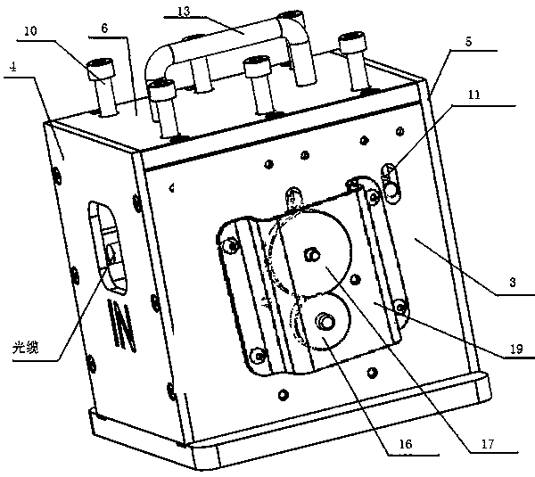
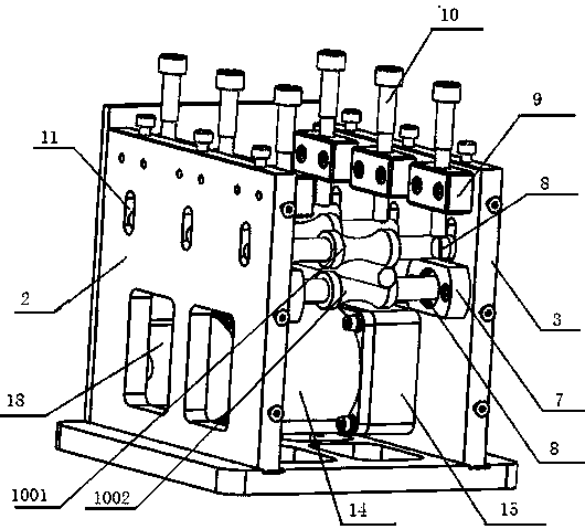
[0032] The invention relates to the field of optical fiber and cable tools, and mainly aims to solve the problems of time-consuming, laborious and certain personal safety hazards in the traditional process of stripping optical cables. This embodiment discloses a specific embodiment of a fully automatic adjustable portable optical cable stripper. The optical cable stripper mainly includes a base 1, a left cover 2 and a right cover 3 fixed to the base 1, and a on the drive mechanism.

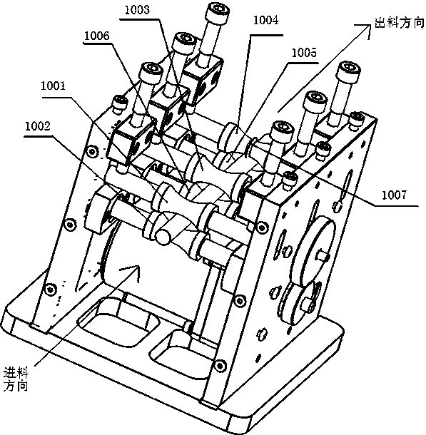
[0033] There are 3 roller sets rotatably connected between the left cover plate 2 and the right cover plate 3 above the driving mechanism. Note: the present invention is not limited to 3 roller sets, but can be 4 roller sets or 5 roller sets Group. The three roller groups are arranged in parallel between the left cover plate 2 and the right cover plate 3. The roller group includes two rollers arranged symmetrically up and down. Thick middle thin roller structure. In this embodiment, the 3 rolle...

Embodiment approach 2

[0042] This embodiment is a further optimization of Embodiment 1, and the specific optimization solution is: the rollers located above the roller group in Embodiment 1 are arranged in a structure that can be adjusted up and down in height. That is, on the left cover 2 and the right cover 3, the positions corresponding to the two ends of the rollers (the first driven roller 1001, the third driven roller 1003, and the fourth driven roller 1004) located above the roller group Offer vertical strip groove 11, on the first driven roller 1001, the 3rd driven roller 1003, height adjusting device is set on the 4th driven roller 1004, the first driven roller 1001, the 3rd driven roller Both ends of the driving roller 1003 and the fourth driven roller 1004 slide up and down in the bar-shaped groove 1004 through the height adjusting device.

[0043] The height adjusting device includes a plurality of bolt bearing seats 9 fixed on the left cover plate 2 and the right cover plate 3 and bolt...


PUM


Abstract

The invention relates to the field of optical fiber cable tools and discloses a full-automatic adjustable and portable optical cable stripping device. The stripping device comprises a base, a left cover plate, a right cover plate and a driving mechanism, wherein at least three parallel rolling shaft groups are rotationally connected between the left cover plate and the right cover plate; each rolling shaft group comprises two rolling shafts that are arranged symmetrically vertically; the two ends of the rolling shafts are sunken to centers of the rolling shafts through an arc to form rolling shaft structures that are thick on two sides and thin in the middle; the upper and lower rolling shafts are in close contact with an inserted optical fiber cable; the driving mechanism is connected with one rolling shaft; the rolling shaft is a driving rolling shaft; the other rolling shafts are driven rolling shafts; and a convex cutting edge is circumferentially arranged in the center of the rolling shaft close to a discharge direction of the optical fiber cable stripping device. Compared with the prior art, the driving rolling shaft is driven to rotate; stable and uniform power is provided;stress uniformity of the stripped optical fiber cable is effectively ensured; the disadvantages of nonuniform exertion, insufficient force and the like during manual operation are overcome; and the damage of the optical fiber cable due to manual misoperation is effectively avoided.

Description

technical field [0001] The invention relates to the field of optical fiber cable tools, in particular to a fully automatic adjustable portable optical cable stripper. Background technique [0002] With the advancement of the construction of the National Energy Internet, the power communication optical cable is used as the transmission channel of the power communication system, and the requirements for the communication transmission quality of the optical cable are constantly improving. Optical cable splicing is an essential part of optical fiber communication. How to reduce the splicing loss caused by optical cable stripping and comprehensively improve the quality of optical cable splicing has become an important problem that needs to be solved urgently. [0003] In the traditional process of stripping the optical cable, two people usually use a utility knife to directly strip the optical cable. Due to the large number of optical fibers in the optical cable, small diameter, ...

Claims


Application Information

Patent Timeline
Patent Type & Authority Applications(China)
IPC IPC(8): G02B6/245
CPCG02B6/245
Inventor 严宇史雪涛陈震徐青王巍巍王震
Owner 国网江苏省电力有限公司淮安供电分公司
Why Eureka
Try Eureka