Pixel driving circuit and driving method thereof and display device

A pixel drive circuit and drive circuit technology, applied to static indicators, instruments, etc., can solve the problems of poor uniformity of display brightness and complex control signals of display devices

Pending Publication Date: 2020-07-31
BOE TECH GRP CO LTD
View PDF7 Cites 3 Cited by
  • Summary
  • Abstract
  • Description
  • Claims
  • Application Information

AI Technical Summary

Problems solved by technology

[0004] The purpose of the present invention is to provide a pixel driving circuit, its driving method, and a display device, which are used to solve the problem of complex control signals required by the existing pixel driving circuit and the problem caused by threshold voltage drift of the driving transistor in the pixel driving circuit. The problem of poor display brightness uniformity of display devices

Method used


Image

  • Pixel driving circuit and driving method thereof and display device
  • Pixel driving circuit and driving method thereof and display device
  • Pixel driving circuit and driving method thereof and display device

Examples


Embodiment Construction

[0071] In order to further illustrate the pixel driving circuit, its driving method, and the display device provided by the embodiments of the present invention, a detailed description will be given below in conjunction with the accompanying drawings.

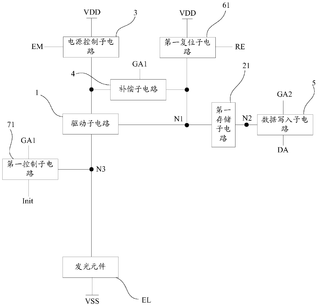
[0072] see figure 1 , an embodiment of the present invention provides a pixel driving circuit for driving a light-emitting element EL, and the pixel driving circuit includes:

[0073] A driving sub-circuit 1, the driving sub-circuit 1 is used to control on or off the connection between the first end of the driving sub-circuit 1 and the second end of the driving sub-circuit 1 under the control of its control terminal, The second end of the driving sub-circuit 1 is connected to the light emitting element EL;

[0074] A first storage sub-circuit 21, the first terminal of the first storage sub-circuit 21 is connected to the control terminal;

[0075] The power supply control sub-circuit 3 is respectively connected to the light em...


PUM


Abstract

The invention provides a pixel driving circuit and a driving method thereof and a display device, relates to the technical field of display, and aims to solve the problems that a pixel driving circuitis complex in control signal and poor in display brightness uniformity of the display device due to threshold voltage drift. In the pixel driving circuit, a first end of a first storage sub-circuit is connected with a control end; the power supply control sub-circuit is connected with the light-emitting control signal line, the first power line and the first end of the driving sub-circuit; the compensation sub-circuit is connected with the first grid line, the control end of the driving sub-circuit and the first end of the driving sub-circuit; the data writing sub-circuit is connected with the second end of the first storage sub-circuit; and the first reset sub-circuit is connected with the reset signal line, the first power line and the control end of the drive sub-circuit. The first control sub-circuit is connected with the first grid line, the initialization signal line and the second end of the driving sub-circuit. The pixel driving circuit provided by the invention is used for driving the light-emitting element to emit light.

Description

technical field [0001] The present invention relates to the field of display technology, in particular to a pixel driving circuit, a driving method thereof, and a display device. Background technique [0002] AMOLED (Active-matrix Organic Light-Emitting Diode, active-matrix organic light-emitting diode) display device has many advantages such as self-luminescence, ultra-thin, fast response speed, high contrast ratio, wide viewing angle, etc., and it is a display device that has received widespread attention at present. . [0003] This AMOLED display device includes a plurality of pixel driving circuits and a plurality of light emitting elements, and the pixel driving circuits are used to drive corresponding light emitting elements to emit light, thereby realizing the display function of the AMOLED display device. However, the existing pixel driving circuit needs complex control signals, and the driving transistor in the pixel driving circuit has the problem that the display...

Claims


Application Information

Patent Timeline
Patent Type & Authority Applications(China)
IPC IPC(8): G09G3/3225
CPCG09G3/3225G09G2310/0286G09G3/3275G09G3/3233G09G2300/0819G09G2300/0852G09G2300/0861G09G2320/045G09G2310/0251G09G2310/0262G09G2300/0408G09G2300/0426G09G2300/0842G09G2310/0297G09G2310/061G09G2310/08G09G2320/0233G09G2330/021G11C19/28
Inventor 于洋
Owner BOE TECH GRP CO LTD
Why Eureka
Try Eureka