Quick circuit breaker and novel drop-out quick breaker

A rapid circuit breaker and separate technology, which is applied to circuit breaker components, high-voltage air circuit breakers, circuit breaker contacts, etc., can solve the problems that the arc cannot be blown and cooled effectively, the arc suppression tube is easy to expand due to moisture, and the volume is large , to avoid electrical fire and electrical explosion, to avoid reclosing failure, and to achieve the effect of high response sensitivity

Pending Publication Date: 2020-08-11
中船安智(湖北)科技有限公司
View PDF1 Cites 1 Cited by
  • Summary
  • Abstract
  • Description
  • Claims
  • Application Information

AI Technical Summary

Problems solved by technology

[0005] 1. When a short-circuit fault occurs in the back-stage equipment, the time before the melt breaks the arc is long, and there is a great possibility that the melt cannot be fused before the outlet switch of the substation cuts off the fault current, resulting in the failure of the drop-out fuse to be isolated correctly. At the point of failure, when the line is reclosed, the faulty equipment is short-circuited again, resulting in the failure of line reclosing and a power outage across the line
[0006] 2. Affected by the arc extinguishing medium and the gas-producing material on the inner wall of the melting tube, the gas production is small and the rate is low. When the arc is generated, the arc cannot be blown and cooled effectively, resulting in poor arc extinguishing ability
[0007] 3. Drop-out fuses are generally installed outdoors. Affected by the wind and rain in the natural environment, the arc suppression tube in the melting tube is prone to moisture expansion, resulting in inner diameter reduction or blockage.
[0012] The above-mentioned patent uses the power of gunpowder explosion to blow the fuse directly. Although this method is direct and fast, but the gunpowder is installed on the guide bar, under the influence of the electromagnetic field generated by the changing high current, it may cause the explosion of the gunpowder and cause malfunction. The guide bar will generate heat under the action of changing high current, and it may also cause the explosion of gunpowder, resulting in malfunction; the failure of the entire device, resulting in serious losses
The above-mentioned patent adopts the method of blasting and turning the guide row to form a fracture, which requires a large space, so the product is too large
In addition, after the switch is exploded, the entire switch needs to be replaced, and the cost of use is too high

Method used


Image

  • Quick circuit breaker and novel drop-out quick breaker
  • Quick circuit breaker and novel drop-out quick breaker
  • Quick circuit breaker and novel drop-out quick breaker

Examples


Embodiment Construction

[0044]In order to make the object, technical solution and advantages of the present invention clearer, the present invention will be further described in detail below in conjunction with the accompanying drawings and embodiments. It should be understood that the specific embodiments described here are only used to explain the present invention, not to limit the present invention.

[0045] Figures 1 to 6 The structural features of this patent are specifically shown, combined below figure 1 with Image 6 Embodiments of the present invention will be described in detail.

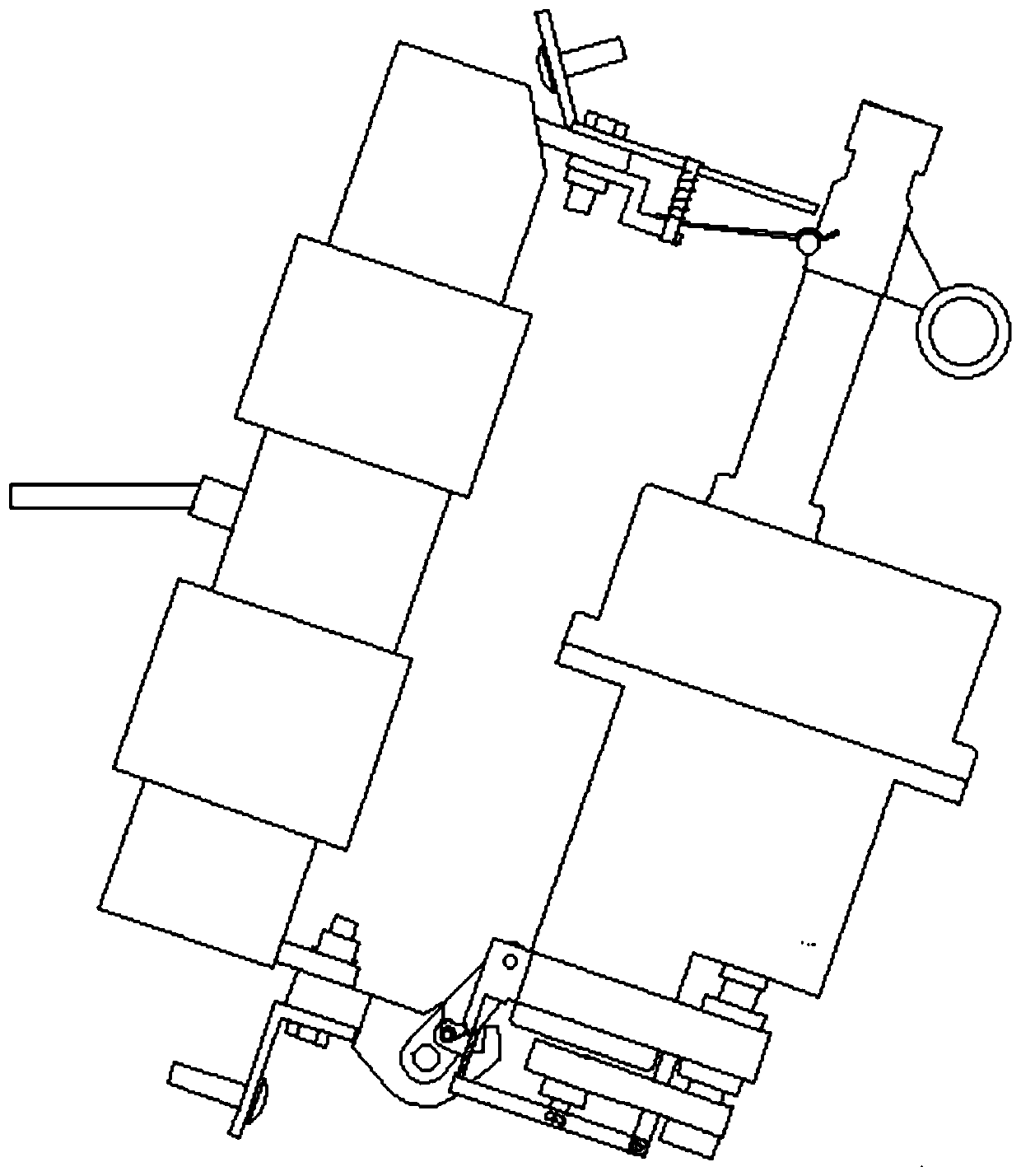
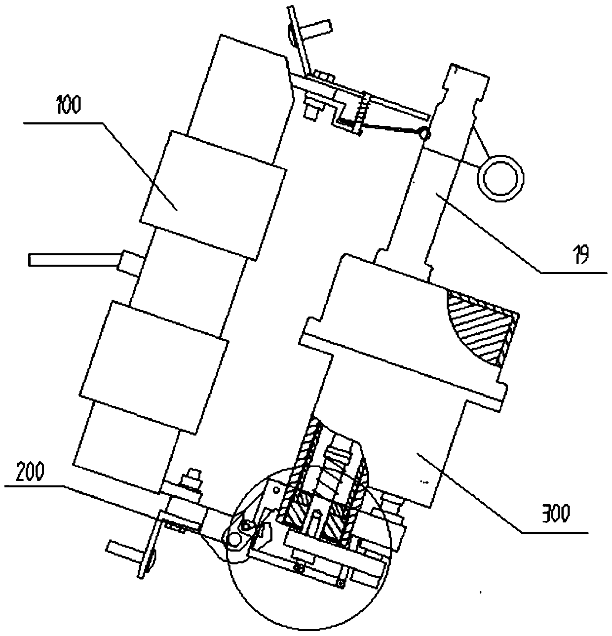
[0046] A novel drop-type quick breaker includes a base 100 , a drop mechanism 200 and a quick breaker 300 .

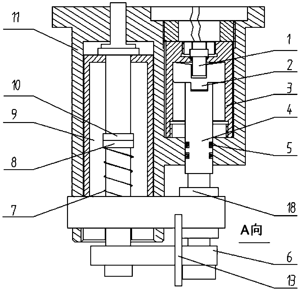
[0047] The fast circuit breaker 300 includes a detachable conductive structure, a push mechanism and a detection control module; the detachable conductive structure includes an insulating shell 11, a static contact 10 and a moving contact 8, and the insulating shell 11 is provided with Vacuum chambe...


PUM


Abstract

The invention relates to a quick circuit breaker and a novel drop-out circuit breaker. The novel drop-out quick breaker comprises a base, a drop-out mechanism and a quick circuit breaker, wherein thequick circuit breaker comprises a separable conductive member structure, a pushing mechanism and a detection control module. The circuit breaker has the advantages of being simple in structure, reliable in work and capable of achieving instantaneous circuit breaking.

Description

technical field [0001] The invention relates to a circuit breaker, in particular to a quick circuit breaker and a drop-type quick breaker based on vacuum arc extinguishing technology. Background technique [0002] At present, drop-out fuses are installed in medium and low-voltage distribution lines and distribution transformers as short-circuit protection switches, which can reduce the scope of power outages, because they have an obvious disconnection point and have the function of isolating switches. Create a safe working environment and improve the safety of maintenance personnel. It is installed on the distribution transformer and can be used as the main protection of the distribution transformer. It is widely used in medium and high voltage distribution lines and distribution transformers. [0003] The working principle of the drop-out fuse is that the moving contacts at both ends of the fuse tube are fastened by the fuse (melt), after pushing the upper moving contact i...

Claims


Application Information

Patent Timeline
Patent Type & Authority Applications(China)
IPC IPC(8): H01H71/10H01H73/04H01H3/24H01H33/66
CPCH01H3/24H01H33/66H01H71/10H01H73/04
Inventor 黄生华丁建龙王国博蔡昊贾云东许三祥吕晓明
Owner 中船安智(湖北)科技有限公司
Why Eureka
Try Eureka